Generic Configuration Model
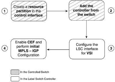
| Before jumping into specific configurations, we will start by building a generic configuration model, removing the specifics and concentrating on the shared structure. The tasks required for LSR and eLSR bringup and setup are the same in all platform implementations, but they have different command sets. The key here is to understand the ideas and interconnect them with the previous chapter's concepts. All the specific configurations will come up naturally as a result of recognizing these general ideas. After all the configuration cases in the following sections, a summary of all the commands and their contexts following this model is included in the later section "Summary of MPLS Configuration Commands." Generic LSR BringupThe common LSR bringup can be broken into four major steps. Steps 1 and 2 are performed in the controlled switch, and Steps 3 and 4 are applied to the LSC. Figure 6-2 shows these steps. Figure 6-2. Generic LSR Bringup Model
In BPX-8600 and IGX-8400 implementations, the first step includes a set of configuration tasks:
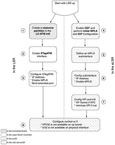
In MGX-8850 platforms, the partition configuration is performed in the RPM-PR card and is automatically sent to the PXM-45 card where the VSI slave lives. In the BPX-8600 and IGX-8400 implementations with an external controller, the controller cannot be added (Step 2 in Figure 6-2) if the control interface is in alarm (such as a Loss of signal [LOS] Red Alarm). MGX-8850 implementations, as well as URM LSC in IGX-8400, do not have this check because the control interface is internal (such as the switch interface in MGX-8850) and cannot be shut down. Steps 2 and 3 can be swapped, such that Step 3 is performed before Step 2. The order presented in this section was chosen so that the LSC configuration would be separated from the controlled switch configuration. Generic eLSR BringupWe can also build a diagram for the eLSR configuration. It starts with the LSR configured and involves two different paths: the LSR side and the eLSR side. Figure 6-3 shows this process. The LSR portion is on the left, and the eLSR part is on the right. Figure 6-3. Generic eLSR Bringup Model
Figure 6-3 is straightforward. However, we can outline some details. Step 1 can also involve bringing up and configuring the physical and ATM layers of the line in the controlled switch. It also includes configuring Class of Service Buffer (CoSB) resources by mapping a Service Class Template (SCT). In an AXSM platform, a Card SCT also must be configured with all the ports administratively down. In Step 3, the IP address is normally unnumbered to a loopback interface to save IP address and LCN resources. Step 7 does not have an equivalent step in the LSR. This is because the VSI interface messages in the LSR learn the logical interface's VPI range and VP tunnel characteristics. On the other hand, in the eLSR, there is no partitioning of resources or VSI protocol, so we need to explicitly configure those parameters. Both configuration commands (vp-tunnel and vpi) have an extra optional parameter that limits the VCI range at the control plane. The parameter vci-range is extremely important in cases where the slave cannot partition VCI resources. Finally, the optional control-vc VPI/VCI configuration must match in both ends. Tag Switching or MPLS?We can configure tag switching using TDP (Tag Distribution Protocol) or MPLS using standards-based LDP (Label Distribution Protocol) on LSRs and eLSRs. As you know, tag switching is a precursor of MPLS. Functionally, LDP is a superset of TDP, and the protocol exchange patterns are almost identical between the two protocols. They have similar messages with different names (Open PIE and Request Bind PIE in TDP correspond to Initialization Message and Label Request Message in LDP) and different UDP ports (for session discovery) and TCP ports (for session establishment). From an operations standpoint, Cisco IOS Parser has tag-switching and MPLS options for most commands. (There are no tag-switching commands for MPLS-specific functions such as a TCP MD5 signature of an LDP session or Path Vector type-length-value [TLV] loop detection.) You can configure either distribution protocol (TDP or standard LDP) with either form of the commands (tag-switching or mpls). One global and interface configuration command configures the use of TDP or LDP. That command is mpls label protocol {ldp|tdp}. The [sub]interface form of the command also has a both option to simultaneously run TDP and LDP. That command has only the mpls form. In this chapter, we will configure standards-based MPLS running LDP using the mpls form of the commands. By default, the commands are saved to configuration in their tag-switching form. This is done for backward compatibility, in case you want to use that configuration on a router without mpls commands. |
EAN: 2147483647
Pages: 149