Quality of Service and Multi-vc
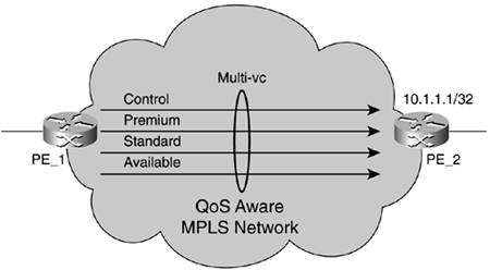
| MPLS support for CoS is inherited from IP CoS support. The MPLS shim header contains the 3-bit Exp field that allows the network to give special treatment to different labeled packets based on the Exp bits. That is why the Exp bits are also called CoS bits. In fact, they are modeled after the IP precedence bits. At the edge, the IP 3-bit precedence header field (or more precisely, the first three bits of the diff-serv code point [DSCP] called class selector) is copied to the Exp bits on label imposition. If the CoS is inferred from the Exp bits, the LSPs are called Exp-inferred PSC LSPs (E-LSPs). PSC stands for per-hop behavior Scheduling Class and refers to a core behavior. The IPv4 header TOS octet (refer back to Figure 4-1) has come a long way from its original definition in RFC 791 to the current definition (at the writing of this book) in RFC 3168. Please refer to Figure 4-17 for the TOS byte historical evolution. However, ATM MPLS encapsulation does not expose the Exp bits. The label-swapping paradigm is performed based solely on the label, which is the VCI field or VPI/VCI combined fields in the ATM cell header. A different method needs to be provided to support QoS on ATM MPLS. This method is called multi-vc, and it is shown in Figure 4-18. Figure 4-18. Multi-vc and ATM MPLS QoS Support
As you can see in Figure 4-18, up to four parallel LVCs are set up per FEC to support up to eight different CoSs, the same as with the Exp bits on frame-based MPLS. How? The Cell Loss Priority (CLP) bit is used in the ATM cell header to differentiate between two different classes per LVC, giving a loss priority. Because the CoS is inferred strictly from the LSP, as there are no Exp bits to use, these LSPs are called Label-only inferred-PSC LSPs (L-LSPs). ATM MPLS QoS follows the DiffServ model, whose architecture is defined in RFC 2475. DiffServ clearly separates and distributes edge behaviors (classification, marking, policing, shaping, metering, and complex per-user and per-application tasks) from core functions (queuing, dropping, and simple tasks). Modeled after the ATM CoS scheme that includes ABR, CBR, VBR-RT, VBR-NRT, and UBR classes, it divides IP traffic into a small number of classes and allocates resources on a per-class basis. At the edge, the classification information is summarized in the DSCP, which gives a new interpretation to the TOS IPv4 header octet and IPv6 traffic class octet as defined in RFC 2474. RFC 2474 recommends the use of eight code points called Class Selector Code Points (any DSCP in the range 'xxx000' where 'x' can either be '0' or '1') to provide a degree of backward compatibility (see Figure 4-17). In accordance, both shim-based and multi-vc-based MPLS QoS approaches provide eight classes of service. Generally speaking, eight different QoS network treatments are enough for almost every network type. You can learn from ATM that the CBR, VBR-NRT, VBR-RT, UBR, and ABR classes have successfully been deployed and are sufficient for all multiservice types of applications. MPLS edge devices can be application-aware and therefore give higher priority to a flow that matches certain applications. This guarantees a QoS in a more dynamic fashion. ATM MPLS QoS is covered in Chapter 7, "Practical Applications of MPLS." |
EAN: 2147483647
Pages: 149