VSI Slave Implementations
| The VSI implementation in BPX-8600 and IGX-8400 switches follows a distributed model. Each BXM and BXM-E card in a BPX-8600 and each UXM, UXM-E, and URM card in an IGX-8400 houses a VSI slave managing the interfaces in that card. MGX-8850 and MGX-8950 Controlled Switches and VSI SlavesThe multiservice switching implementations in PXM-45-based MGX-8850 and MGX-8950 have some variations. They are a bit more complex than the controlled switch architecture, presenting a hybrid VSI slave model. To completely understand the MPLS and PNNI implementations on these switches, you need to understand the switch platform. In a PXM-45-based MGX-8850, the switching is performed in the PXM-45 card. Figure 3-34 shows a simplified hardware overview. Figure 3-34. PXM-45-Based MGX-8850Hardware Overview
The TDM bus is used for bulk distribution. The redundancy bus is not shown in Figure 3-34. For the purposes of switching, NBSMs use the cell buses. (The backplane contains eight cell buses.) The PXM-45 card uses shared memory to switch cells from the cell buses, such as a PXM-1. Examples of NBSMs include all single-high service modules (such as VISM, FRSM, and AUSM) and RPM-PR. BASMs use sets of serial lines called serial buses running to every double-high slot. The PXM-45 card uses cross-point switches to switch cells from the serial buses. Examples of BASMs include all the AXSM and AXSM-E cards and the RPM-XF. The following list shows the switching path in the PXM-45 card for intranode connections:
The following list shows the switching path in the PXM-45 card for internode connections:
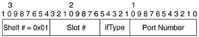
On an MGX-8950 platform, the switching of cells from the cell buses is also performed in the PXM-45/B cards, but the switching of cells from the serial buses is performed in the XM-60 cards. This adds another degree of separation between data traffic and control traffic. The control bus also connects the XM-60 and the PXM-45/B cards. NOTE The MGX-8950 does not support SRM cards or single-high service modules. The only NBSM it supports is RPM-PR. The MGX-8950 also supports only AXSM/B modules (as opposed to AXSM modules, which fail in an MGX-8950). Why is this quick overview important for an understanding of the multiservice switching implementation on these two platforms? The answer is very straightforward: BASMs (AXSM, AXSM-E, and RPM-XF) implement the VSI slave in the card, whereas NBSMs (RPM-PR, VISM, AUSM, FRSM, and CESM) use a centralized slave in the PXM-45 card as a proxy VSI slave. The end result is that the slave model is hybrid; BASMs (also known as Serial Bus Service Modules [SBSMs]) provide the distributed part of the model, and NBSMs (also known as CBSMs) provide the centralized portion of the model. NOTE The preceding paragraphs do not imply that all NBSMs operate in an MPLS or PNNI application. For example, the Circuit Emulation Service Module (CESM) does not fit in any MPLS application. Nevertheless, when a controller such as the LSC, PNNI controller, PAR controller, or any future controller uses an NBSM, it communicates with the VSI slave located in the PXM-45. In an MPLS application, RPM-PR is the NBSM that is used. The PNNI controller can theoretically use FRSM, AUSM, VISM, RPM-PR, and CESM. RPM-PR is the first CBSM with support for SPVCs in PNNI applications. PNNI controller support for other CBSMs on PXM-45 is under investigation. VSI Slaves: Logical Interface NumbersAs you know, the VSI slave is responsible for assigning unique and persistent 32-bit-long LINs that identify each logical port. Even though the VSI master should not make assumptions about the encoding of the LINs, or assume any logic behind it, it is useful for you to understand LIN encoding for low-level troubleshooting. The fact that the VSI master does not associate the LIN with a physical port keeps the networking code platform-independent. A physical descriptor is advertised as an ASCII value from the slave to ease user configuration. Different VSI slaves encode the LIN differently based on the specifics of each platform. In BPX and IGX switches, VSI slaves in BXM and UXM cards, respectively, use a straightforward coding scheme: LINUXMBXM = 0x00AABBCC, where AA is the slot number, BB is the physical port number, and CC is the virtual trunk number or 0 if it is not a virtual trunk. The VSI slaves in AXSM and PXM-45 cards in MGX platforms use a different encoding. Figures 3-35 through 3-37 summarize the LIN assignment in all VSI slaves. Figure 3-35. BXM and UXM LIN Encoding
The BXM and UXM VSI slave LIN encoding is shown in Figure 3-35. Figure 3-35 contains the following field:
The AXSM cards and RPM-XF VSI slave LIN encoding are shown in Figure 3-36. RPM-XF is a serial line-based (as opposed to cell bus-based) RPM for MGX-8850 and MGX-8950. RPM-PR is cell bus-based and does not include a VSI slave module. Figure 3-36. AXSM and RPM-XF LIN Encoding
Figure 3-36 contains the following fields:
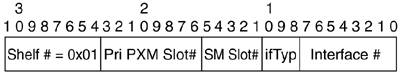
Figure 3-37 shows the PXM-45 and PXM-1E proxy VSI slave LIN encoding. This encoding is used for service modules for which PXM-45 or PXM-1E is a centralized slave. Those include RPM/B, RPM-PR, and NBSM (that is, all cell bus-based service modules [SMs]), as well as internal logical ports. Figure 3-37. PXM-45 and PXM-1E LIN Encoding
Figure 3-37 contains the following fields:
The high-speed Frame Relay Service Module (FRSM-12-T3E3) uses the same LIN encoding as AXSM cards and RPM-XF. As mentioned earlier, the PXM-45 or PXM-45B card in an MGX-8850 platform acts as a centralized slave for cell bus-based service modules. Those service modules include mid-high SMs (such as VISM, FRSM, and AUSM) and RPM-PR cards. The only CBSM supported in the MGX-8950 platform is RPM-PR. The PXM-45 or PXM-45/B has other virtual ports. (In the LIN, the SM slot number is 7.) They are summarized in Tables 3-6 and 3-7.
NOTE The logical interface 7.34 is a logical or virtual port. It does not exist physically in the PXM-45 but is presented as another port to the VSI master application. The need for such a port is as follows: Signaling connections such as UNI and PNNI need to terminate in the PXM-45 for SAR and processing. Those connections are created using VSI messages. Therefore, VSI needs a LIN to reserve and commit those endpoints. Another example is the IPCONN application. This logical interface is the endpoint for SVCs for IP management connectivity to the MGX switch, terminating in the IP stack.
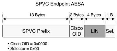
Some clarifications are necessary regarding logical ports 7.35 through 7.38. The PXM-45-UI-S3 back card has two physical clock ports, but four LINs are necessary to uniquely identify the BITS mode of both clock ports. In Chapter 2, "SCI: Virtual Switch Interface," the "Clock Synchronization" section described the mechanism used between the slave (advertising the clock input as a LIN with no connection capabilities) and the NCDP application. The PXM-45 slave understands only LINs, and the VSI set clock commands do not have a field to indicate clock type (BITS T1 versus BITS E1). Four LINs are needed to overcome this limitation where the user can configure four combinations (CLK1 E1, CLK1 T1, CLK2 E1, and CLK2 T1). Emphasizing the ideas presented before, the VSI master does not need to know the logical interface encoding. It treats the LIN as a 32-bit number, not assuming a coding scheme. But the user (who sees the whole picture) needs to know it. LINs are used in different contexts. The most visible example is the construction of the SPVC endpoint AESA, where the switch prefix is prefixed to the LIN to create a unique AESA for SPVCs. See Figure 3-38. Figure 3-38. SPVC Endpoint AESA Construction Using LIN
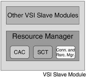
VSI Slaves: Resource ManagementOne of the most important modules in the VSI slave to ensure true multiservice functionality is the Resource Management Module (RMM). The Resource Manager implements the VSI slave's platform-specific or dependent functionality. It is logically divided into different submodules, as shown in Figure 3-39. Figure 3-39. VSI Slave Resource Manager Components
The three constitutive modules of the resource management module are explained in the following list:
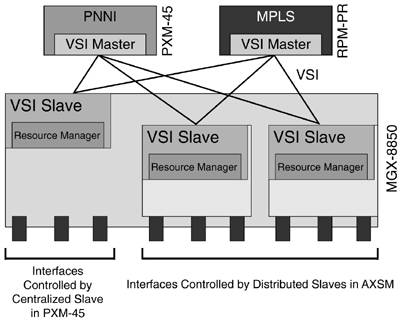
NOTE CAC is performed by the VSI slave. In a PNNI application, the PNNI node originating the source route performs a General Connection Admission Control (GCAC) when creating the Designated Transit List (DTL). GCAC is performed by the PNNI controller. Neither call-acceptance mechanism should differ. If the GCAC algorithm is too permissive compared to the CAC algorithm, unnecessary crank-backs result. If GCAC is too restrictive, it prevents the use of routes with enough resources. NOTE A physical interface consists of one or more logical interfaces. Each logical interface has one or more resource partitions. As an example, Figure 3-40 shows some of the practical differences between a centralized slave and a distributed slave in a PXM-45-based MGX-8850 that uses a hybrid slave model. Figure 3-40. VSI Hybrid Model in a PXM-45-Based MGX-8850
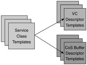
Resources in BASMs are managed by the VSI slave in the card, and resources in NBSMs are managed by the centralized VSI slave in the PXM-45 card, resulting in a VSI hybrid model. VSI Slaves: Connection and Resource ManagerThe Connection and Resource Manager is the third module on the Resource Manager implemented as part of the VSI slave. Different VSI slaves manage and partition different resourcesin particular, BXM and BXM-E cards in a BPX-8600, UXM and UXM-E cards in an IGX-8400 partition VPI space, and bandwidth and LCN resources per VSI resource partition. Indirectly, the QBins (or Class of Service [CoS] buffers) are also partitioned. The AXSM card implementation, however, has finer granularity. The resources that are partitioned per VSI partition are VPI space, VCI space, egress bandwidth, ingress bandwidth, and LCN resources (as well as indirectly partitioning CoS buffers). Compared to BXM and UXM implementations, bandwidth partitioning has one more degree of freedom (direction; the ingress and egress can be different), and it also can partition the VCI space. At first glance, VCI space partitioning might seem unimportant or trivial, but it has significant consequences. Allowing partitioning of resources in a virtual trunk (VP-Tunnel) and assigning those partitions to two different controllers is one of the outcomes. A customer can buy a VPC from a service provider and run MPLS and PNNI over itfor example, MPLS using VCIs between 33 and 32767 and PNNI using VCIs between 32768 and 65535. NOTE If the objective is to limit the VCI space for only one partition, that can be accomplished from the controller, in an MPLS controller or a PNNI controller. Service Class Templates and QoSSCTs are extremely important in multiservice switch implementations because they are the means to provide QoS support. SCTs provide a way of mapping protocol connection parameters (such as MPLS or PNNI traffic parameters) passed in VSI connection setup primitives to extended parameters, usually platform-specific. SCTs provide support for different CoSs. Refer to Figure 2-3 and the paragraph following it in Chapter 2. SCTs are structured in two different templates: VC descriptor templates, with the necessary parameters to establish connections, and Class of Service Buffer (CoSB) descriptor templates, employed to configure the queues that service connections with similar QoS requirements. See Figure 3-41. Figure 3-41. SCT Structure
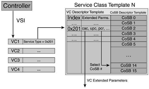
NOTE CoSB is a general designation that sometimes goes by a different name in a different implementation. In BXM cards, CoSBs are also called QBins. The CoSB descriptor template has 16 entries because each virtual interface has 16 CoSBs or QBins. When a controller wants to set up a cross-connect in the controlled switch, the VSI message contains optional traffic parameters, along with a service type specified for the connection, as discussed in Appendix A, "Service Traffic Groups, Types, and Categories." That service type is used as the index into the VC descriptor template to find the extended parameters and program the connection. This process is illustrated in Figure 3-42. Figure 3-42. SCTSimplified Connection Setup Process
The SCTs also include a default service type entry in the VC descriptor template in case an unsupported service type is requested. The VC descriptor templates can have parameters or "columns" that are scaling factors or multipliers of VSI-provided parameters. Other parameters are independent of VSI-provided parameters. The CoSB templates configure the CoSBs. Some of the parameters included in the CoSB template are CLP, EPD, and EFCI thresholds, and EPD and WFQ enable/disable status. In general, SCTs are valid only for VSI-enabled partitions. One of the extended parameters in the VC descriptor template is the CoSB that the traffic type uses. This fact is of great importance because it allows the multiservice switch to use different queues for different service types. In an MPLS multi-vc application, for example (as discussed in Chapters 4 and 7), this allows an LSR to use one queue for "standard" traffic and a different one for "premium" traffic. In the multiservice switching LSR, the forwarding is performed by the controlled switch based on the switching label in part of the VPI/VCI in the cell's header. Yet the queues in the controlled switch are IP-aware. In a PNNI scenario, different queues are used for CBR traffic and UBR traffic, allowing true constraint-based routing. Generalizing this concept, SCTs give the multiservice switch the tools to implement the Core Differentiated Services (DiffServ) architecture (see RFC 2475). The DiffServ architecture defines edge behaviors (classification, marking, policing, and so on) and core behaviors (Per-Hop Behaviors [PHBs], in which the same treatment is applied to all packets with the same DiffServ service class). The building blocks of PHBs are queuing and drop ping. With the SCTs, a multiservice switch can implement per-class queuing and dropping policies, as well as assign a subpartitioned bandwidth allocation to each class. SCTs also allow class type-aware admission control, a building block of Guaranteed Bandwidth Traffic Engineering (GB-TE) or DiffServ-Aware Traffic Engineering (DS-TE), where a connection's class type is signaled. In essence, the CoSB templates in the SCT indirectly partition queue resources. Different SCTs are suited to different applications (typical interface uses). There are nine predefined SCTs, covering MPLS-only interfaces, PNNI-only interfaces with and without policing, and different combinations of simultaneous MPLS and PNNI interfaces. SCT characteristics are summarized in Table 3-8.
NOTE Not all SCTs are implemented in all platforms. SCT 1 supports only MPLS service. The rest of the SCTs, from 2 to 9, are identical pairs, except that the even SCTs (2, 4, 6, and 8) have policing on, and the odd SCTs (3, 5, 7, and 9) do not have policing for ATMF service types. SCTs 2 and 3 support only ATM Forum types (such as PNNI), and the rest support some combination of MPLS and PNNI service types. On BPX and IGX slaves, AutoRoute service types use some QBins. Therefore, some of the SCTs implement reduced support for a certain service category, such as MPLS or ATMF, meaning that all service types use only two CoSBs or QBins. Conversely, on AXSM slaves, the SCTs that simultaneously support MPLS and PNNI map the service categories to different CoSBs, providing full support for MPLS and PNNI simultaneously. In MPLS-only SCT (SCT 1) or PNNI-only SCTs (SCTs 2 and 3), no support is provided for the other service categories. This means the service types in those service categories use the same CoSB or QBin as the default service type, all mapped to one single CoSB. The VSI specification requires that unknown service types be mapped to the default service type. Different platforms implement SCTs differently:
Differences also exist from a configuration perspective. BPX-8600 and IGX-8400 have very few configuration parameters using SwSW commands. The VC descriptor template cannot be configured. MGX-8850 SCTs, on the other hand, can be modified offline using Cisco WAN Manager (CWM) and uploaded to the PXM-45 hard drive. |


EAN: 2147483647
Pages: 149
- Article 324 Flat Conductor Cable Type FCC
- Article 424: Fixed Electric Space Heating Equipment
- Example No. D6 Maximum Demand for Range Loads
- Example No. D8 Motor Circuit Conductors, Overload Protection, and Short-Circuit and Ground-Fault Protection
- Example No. D10 Feeder Ampacity Determination for Adjustable-Speed Drive Control [See 215.2, 430.24, 620.13, 620.14, 620.61, Tables 430.22(E), and 620.14]