MPLS Implementations
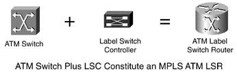
| This section describes in detail all the different MPLS implementations in multiservice switching devices. It starts by defining the label switch controller (LSC) and the general MPLS switch architecture and concepts, as well as summarizing the MPLS switch realizations. The rest of the section explores each implementation. Label Switch ControllerThe controller in an MPLS application is called a label switch controller. It contains both the networking modules (routing protocols, LDP, and so on) and the VSI master modules. The LSC and the ATM-controlled switch together constitute a single Label Switch Router (LSR), as shown in Figure 3-1. Figure 3-1. Multiservice Switching LSR
In essence, the LSC is a router. Moreover, it is an MPLS router, with all the functions of an LSR plus extra functionality to control the switch using VSI. The LSC's primary function is to set up the ATM switch so that the LSC is not in the data path. Internally, each interface is represented with a Cisco IOS interface descriptor block or IDB (a data structure in Cisco IOS software that represents the hardware interface). Within the LSC, each interface in the controlled switch is represented as a new type of virtual interface called the extended MPLS ATM (XmplsATM IDB) interface. This concept allows the existing MPLS applications to control and interact with an ordinary ATM interface. Two different implementations were considered for the representation of the ports in the slave switch: implementations in which the XmplsATM IDBs were all subinterfaces of the control interface, and implementations in which the XmplsATM IDBs were an entirely new type of IDB. The former was discarded mainly because interfaces on the switch have one address space per interface and can have overlapping VPIs/VCIs. Each LC-ATM interface has its own label space. As such, XmplsATM interfaces were implemented as a new type of full (hardware and software) IDBs. XmplsATM interfaces expose the LC-ATM interface in the controlled switch. The XmplsATM interfaces are similar to ATM router interfaces in most respects. However, XmplsATM interfaces support only MPLS, not Q.2931 signaling, LANE, or Classical IP (see RFC 1577). In fact, most ATM functions and commands are disabled in an XmplsATM interface. Internally, it is not seen as an ATM interface. The following functions are present in an ATM interface but not in an XmplsATM interface:
Functionally, when a packet is given to the XmplsATM device for transmission, it is redirected to the control interface. The XmplsATM interface has no hold queue; the packet might be put in the control interface's hold queue if that interface is congested. Introducing the extended ATM interface is not the only different concept we need to review concerning MPLS implementation in multiservice switches. The next idea we need to explore is the categorization of the virtual circuits (VCs) in the LSC/switch picture. From the LSC perspective, we can divide the VCs into three categories:
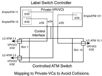
NOTE Other VSI cross-connects in the controlled switch are invisible to the LSCthe VSI slave-slave cross-connects in a VSI distributed model. Given the similarities between the control-vcs and terminating LVCs, they are often called terminating VCs. There are differences, though. For example, control-vcs are bidirectional, and LVCs are unidirectional. All data between the LSC and the controlled switch (only for terminating VCs) traverses the control interface. An additional port on the router and a corresponding port on the switch serve this purpose. One important thing to mention is that all terminating VCs have one leg of the cross-connect in the controlled switch. These cross-connects can all terminate in different switch interfaces with the same VPI/VCI pair. (The control-vc can have the default VPI/VCI values of 0/32, and for terminating LVCs, each LC-ATM interface has its own label space.) The other leg of the cross-connects terminates on the LSC passing through only one control interface (between the LSC and the switch) so that its cells are segmented and reassembled (SARed) and processed by the LSC. A problem arises with the need to avoid collisions of VPIs/VCIs on the control interface. To solve that problem, terminating VCs are remapped inside the switch cross-connect on the control interface. These remapped VCs are called private VCs. Inside the LSC software, private VCs are mapped back to their original values so that the MPLS control plane observes the correct values (values used in the actual interface in the switch, usually called external VPI/VCI). To support the notion of private VCs, a new encapsulation type is used in XmplsATM interfaces, indicating that a packet received in this VC is actually destined for an XmplsATM VC. See Figure 3-2. Figure 3-2. Mapping of Terminating VCs to Avoid VPI/VCI Collisions in the Control Interface
The cross-connects shown in Figure 3-2 are set up using VSI. Therefore, the VPI used in the control interface (x in the figure) is within the VPI range specified in the corresponding partition in that interface. NOTE VSI runs between the LSC and the controlled switch through the control interface. The LSC-switch pair forms the MPLS LSR. The control interface is invisible to neighboring LSRs. From their perspective, the control interface can be thought of as a bus that is internal to the LSR. LDP and IP routing see a single LSR, not the LSC-switch pair. The LSC is the controller used on the implementations of MPLS multiservice switches. Before we get into the details, look at Table 3-1, which summarizes the different MPLS LSRs, specifying the controlled switches and the corresponding LSC implementation.
Normally, the edge Label Switch Router (eLSR, also called a Label Edge Router [LER]) is an external router connected to an LC-ATM interface in the LSR. An eLSR also has two special implementations, in which the edge functionality resides in a router blade inside the controlled switch. In these cases, the router card can act as either an LSC or an eLSR. One last implementation exists in which the eLSR resides in a router card inside an ATM switch without LSR functionality. These three cases are summarized in Table 3-2.
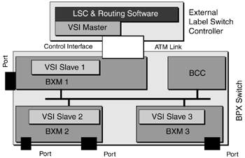
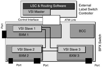
BPX-8600 MPLS ImplementationsThe BPX-8650 IP + ATM switch is an MPLS-enabled switch. It consists of a BPX-8620 ATM switch with distributed VSI slaves in BXM or BXM/E cards (processor-based service cards) and a Cisco 72xx-based LSC including the VSI master modules. In the MPLS architecture, the BPX-8620 switch together with the LSC acts as an ATM LSR. NOTE The 7200 router-based LSC also can act as an eLSR concurrently with the LSC functionality. However, it is strongly recommended that the eLSR functionality on a 7200 router not be used when it serves as an LSC. The eLSR functionality is enabled by default. You will see how to disable it in the sections named "Disabling Headend LVCs" and "Disabling Tailend LVCs" in Chapter 6, "MPLS Implementation and Configuration." The control link uses an ATM port adapter in the LSC and an ATM port in the BPX switch. As you know, all communication between the switch and the LSC is performed over ATM VCs. The following figures help you better understand the ATM channels involved. Figures 3-3 through 3-7 show the control and data paths in an LSC-controlled BPX-8600 MPLS LSR. Figure 3-3. BPX-8600 LSRControlled Switch Configuration Path
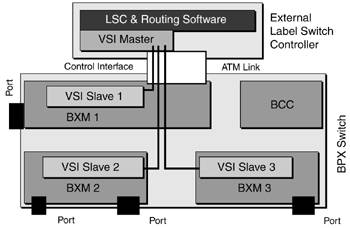
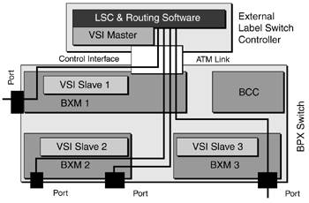
Figure 3-3 shows the controlled switch configuration over comm-bus. In the BPX platform, the BCC card runs the switch software. It communicates with the different cards that have comm-bus messaging. Figure 3-4 shows the VSI master-slave VCs, part of the VSI control path. These channels are used for master-slave VSI communication. There is one master-slave VC from the VSI master in the LSC to each slave in active BXM cards. In the control interface, the default VPI/VCI is 0/40. Figure 3-4. BPX-8600 LSRVSI Master-Slave Channels
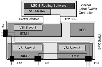
Figure 3-5 shows the VSI interslave cross-connect, completing the VSI control path. A distributed slave model has a full mesh of cross-connects among the slaves, going from each slave in an active BXM card to every other slave in all other active BXM cards. Figure 3-5. BPX-8600 LSRVSI Slave-Slave Cross-Connects
Figure 3-6 shows LDP routing signaling VCs, which are the MPLS control path. Using VSI, the LSC creates the control-vcs. They are used for unlabeled IP traffic, such as IGP updates and TDP/LDP. They are bidirectional, and by default, the VPI/VCI used is 0/32 in the LC-ATM interfaces. In the control interface, private VCs are used. Figure 3-6. BPX-8600 LSRUnlabeled (non-MPLS) Traffic Connections
The networking software uses the information gathered with these VCs to create LVCs. Figure 3-7 shows the label-controlled cross-connects, which are the data path. Creating LVCs is the objective. Using VSI, the LSC creates the unidirectional cross-connects in the controlled switch. Figure 3-7 clearly shows that as soon as the LVCs are set up, the LSC does not touch the data. Figure 3-7. BPX-8600 LSRLVCs
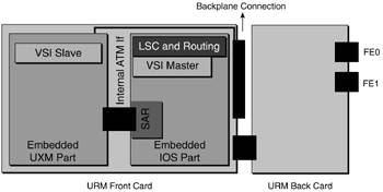
NOTE Figures 3-3 through 3-7 help you understand the VCs and cross-connects involved in the LSR. They are not for studying a BPX-8600 from a switching perspective. The BCC card in the BPX-8600 not only runs the switch software but also houses the switch fabric (19.2 Gbps peak cross-point matrix). Every cross-connect inside the BPX-8600 is switched in the active BCC. IGX-8400 MPLS ImplementationsThe LSC is the controller used in MPLS applications. The IGX family of switches has two different LSC implementations: an external LSC and a co-controller card LSC. In both cases, the slave model is distributed. Every UXM, UXM-E, and URM card has one VSI slave implementation. IGX-8400 with an External LSCThe IGX 8400 family of switches (IGX-8410, IGX-8420, and IGX-8430, with 8, 16, and 32 slots, respectively) can be MPLS-enabled with an external Cisco 72xx-based LSC in the same way a BPX-8600 is. From a multiservice switch perspective, the LSC-controlled IGX architecture is the same as the LSC-controlled BPX discussed earlier. However, the IGX and BPX platforms have different switching technologies and capacities, slots, port densities, and so on. IGX-8400 with a Co-Controller Card LSCThe LSC controlling an IGX switch has another implementation. For this other implementation, the LSC is located on the switch on a separate card, with the URM co-controller card. NOTE The URM card can be configured to act as an LSC controlling the IGX or as an eLSR. This feature enables the deployment of MPLS networks without deploying separate MPLS-capable routers. LSC and eLSR functionality in the same URM card is strongly discouraged. From a very high-level perspective, the Universal Router Module (URM) card looks like Figure 3-8. Figure 3-8. Universal Router Module
Seen as a whole, the URM hosts the networking protocols (IP routing, dynamic MPLS, and traffic engineering), a VSI master module, and a VSI slave module. The following figures illustrate the channels used in a URM-LSC-controlled IGX. For completeness, two URM cards are present in the figures:
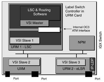
Figure 3-9 shows the configuration path over the C-bus, which is the platform control path. In the IGX platform, the NPM card runs the switch software. It communicates with the different cards with C-bus messaging. Figure 3-9. IGX-URM LSRControlled Switch Configuration Path
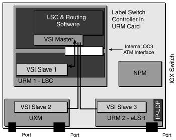
Figure 3-10 shows the VSI master-slave VCs. These channels are used for master-slave VSI communication. There is one master-slave VC from the VSI master in the URM's LSC to each slave in active UXM or eLSR-URM cards. Figure 3-10. IGX-URM LSRVSI Master-Slave Channels
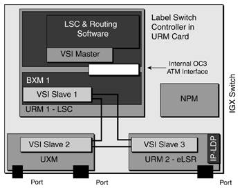
There is also master-slave VSI communication inside the URM that acts as the LSC. The communication between the UXM portion and IOS portion inside a URM card uses the IPC (interprocess communication) VC (VPI/VCI = 0/1023), not a specific VSI VC. NOTE In a URM card, VPI/VCI = 0/1023 cannot be used for controller addition in an MPLS LSC application or in a URM port because it's used for IPC. It can be used in a UXM with an external controller. Figure 3-11 shows VSI interslave cross-connects. Together with the VSI master-slave VCs, they form the VSI control path. These VSI slaves also follow a distributed model. Therefore, there's a slave-to-slave cross-connect from every slave in an active UXM or URM card to every other slave in active UXM or URM cards. Figure 3-11. IGX-URM LSRVSI Slave-Slave Cross-Connects
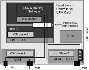
Figure 3-12 shows the LDP routing signaling VCs, which are the MPLS control path. Using VSI messages, the LSC creates the control-vcs that are used for untagged IP traffic (IGP updates and TDP/LDP). The VPI/VCI used by default is 0/32 in the LC-ATM interfaces. Figure 3-12. IGX-URM LSRUnlabeled (non-MPLS) Traffic Connections
In UXM LC-ATM interfaces, those control-vcs terminate in the next LSR or eLSR. In a URM-based eLSR, the control-vc terminates in the embedded router. Figure 3-13 shows the label-controlled cross-connects that make up the data path. Using VSI, the URM-LSC creates LVC cross-connects. No transit LVCs traverse the URM-eLSR, only headend or tailend VCs. Figure 3-13. IGX-URM LSRLVCs
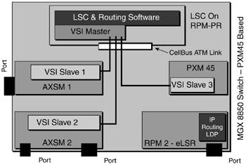
After the LVCs are set up, the URM-LSC does not touch the data. NOTE An IGX-8400 like the one shown in Figures 3-9 through 3-13 with one URM card with LSC functions and another URM card with eLSR functions is seen from other LSRs as two different pieces of equipment: one LSR (which is made up of the URM-LSC and UXM cards with LC-ATM interfaces and VSI slaves) and an eLSR (which is the URM-eLSR). MGX-8850 and MGX-8950 MPLS ImplementationsPXM-45-based MGX multiservice switches natively support MPLS LSR functionality in two different ways that provide a one-box solution in a very efficient way: by placing the LSC functionality in route processor module (RPM) cards, with the same networking modules and VSI master modules as in the BPX and IGX implementations. Both RPM-PR and RPM-XF cards can perform LSC or eLSR functions in an MGX-8850 and LSC functionality in an MGX-8950. To fully understand the MPLS LSR and eLSR implementations in MGX-8850 and MGX-8950 IP + ATM switches, you need to understand not only the LSC implementation but also the VSI slave architecture. From a switch perspective, PXM-45-based MGX switches present a VSI hybrid model. Each BASM (Broadband ATM Service Module, such as AXSM cards and RPM-XF) presents a VSI slave inside the card. Alternatively, the PXM-45 and PXM-45/B cards implement a VSI slave acting as a proxy VSI slave for CBSMs (Cell Bus Service Modules, such as RPM-PR). Details on the VSI slave architecture are given in the later section "MGX-8850 and MGX-8950 Controlled Switches and VSI Slaves." MGX-8850 and MGX-8950 with an RPM-PR-Based LSCThis section explores the VCs, cross-connects, and relationships among the different functional modules. This section's figures are based on an RPM-PR-based LSC and eLSR, so the PXM-45 card acts as a proxy slave for the LSC as well as for the eLSR. Figure 3-14 depicts the VSI master-slave VCs. These channels are used for master-slave VSI communication. There is one master-slave VC from the VSI master in the LSC to each slave in active AXSM cards, as well as to the active PXM-45 card. Figure 3-14. MGX-8850 and MGX-8950 LSRVSI Master-Slave Channels
LSC controller-to-slave communication is performed using virtual circuit connections (VCCs) for VSI sessions, as shown in Figure 3-14. These cross-connects have well-known VPI/VCI pairs, on both the RPM-PR side and the BASM side. (PXM-45 acts as a proxy VSI slave for Narrow Band Service Modules [NBSMs].)
Table 3-3 summarizes the well-known VPI/VCI values for RPM-PR and RPM-XF.
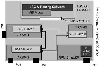
NOTE Management VCs are used for IPC. The IPC protocol introduced the concept of IPC zones to accommodate the ability to house multiple active RPM cards. Figure 3-15 shows VSI interslave communication. This implementation uses a hybrid slave model, with distributed VSI slaves in all BASMs as well as a centralized slave in the PXM-45 for all NBSMs (such as the RPM-PR acting as an eLSR). Figure 3-15. MGX-8850 and MGX-8950 LSRVSI Slave-Slave Path
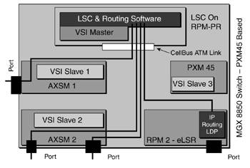
As such, communication among all slaves is needed. But this case is different from the previous two because there are no slave-to-slave VCs or cross-connects. Slave-to-slave communication is accomplished using IPC (which is why Figure 3-15 has an arrow). For slave-to-slave VSI communication, each VSI slave (including the proxy VSI slave) creates an IPC endpoint. This is completely transparent to the VSI master located in the RPM-PR. The name bound to this endpoint is formed from the string vsis concatenated with the slave ID (in hexadecimal format). For example, an AXSM card in slot 3 binds the IPC endpoint to the name vsis3, and an AXSM-E in slot 12 uses the name vsisC. So the inter-slave communication can be seen as VSI over IPC. Figure 3-16 shows the LDP routing signaling VCs. As with the previous cases, the first VCs that are created using VSI are the control-vcs. Figure 3-16. MGX-8850 and MGX-8950 LSRUnlabeled (non-MPLS) Traffic Connections
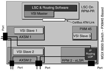
In AXSM LC-ATM interfaces, those control-vcs terminate in the next LSR or eLSR. In an RPM-based eLSR, the control-vc terminates in the RPM. Figure 3-17 shows the label-controlled cross-connects, which as data paths are the ultimate goal. Using VSI, the RPM-LSC creates LVCs. Figure 3-17. MGX-8850 and MGX-8950 LSRLVCs
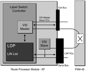
For the eLSR endpoints, the VSI master sends the setup messages to the PXM-45 slave. After the LVCs are set up, the RPM-LSC does not touch the data. MGX-8850 and MGX-8950 with an RPM-XF-Based LSCRPM-XF uses a different architecture and technology than RPM-PR, providing much higher performance. RPM-XF is based on Parallel Express Forwarding (PXF), a new technology, and a Toaster Micro-Controller (TMC) processor. RPM-XF is a BASM (using the serial bus for data), but also with access to the cell bus for control traffic. So RPM-XF manages two interfaces to the PXM-45. RPM-XF separates VSI traffic (in the cell bus) from TDP signaling and LVCs (in the serial bus), providing complete separation of control and user traffic. RPM-XF supports the OC-12 Packet Over Sonet (POS) back card and the Gigabit Ethernet (GigE) back card (as well as a console back card with two Fast Ethernet ports for management). As mentioned earlier, RPM-XF hosts both the LSC and VSI slave. The in-card VSI slave manages the partition in the serial bus interface. It is responsible for all setup/teardown operations in the serial bus interface. The RPM-XF architecture is shown in Figure 3-18. Figure 3-18. RPM-XF
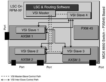
In Figure 3-18, the VSI master-slave VCs use the cell bus. LDP VCs as well as LVCs use the serial bus. The communication between the VSI master in the RPM-XF and the embedded VSI slave controlling the interface to the serial bus is cross-connected in the PXM-45. The LDP VC shown in the figure was created by the VSI slave in the RPM-XF, as indicated by the arrow. From an operation/configuration point of view, the differences between RPM-PR and RPM-XF are minimal. RPM-XF has a superset of commands. The RPM-XF is the first RPM module that supports LSC and eLSR functionality coexistence on the same RPM. This is achieved by separating control and user data in different hardware paths, protecting control data during user congestion in the switching paths, creating the control-vc with the highest-priority service type, and other mechanisms. Figures 3-19 and 3-20 show the channels used in an RPM-XF-based LSC. Figure 3-19. RPM-XFVSI Communication
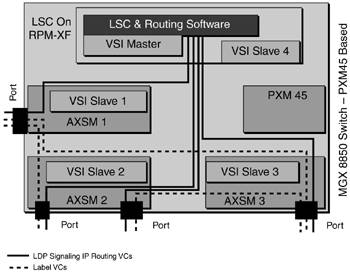
Figure 3-20. RPM-XFLDP and Routing VCs and LVCs
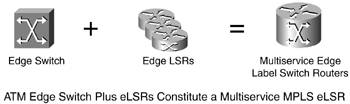
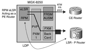
The complete VSI control plane comprised of VSI master-slave and VSI slave-slave communication is shown in Figure 3-19. It is important to note in Figure 3-19 that there is VSI communication within the RPM-XF card. Figure 3-20 shows the MPLS control plane VCs used by unlabeled traffic such as LDP signaling and IP routing, as well as label VCs that create the data path. eLSR Functionality in an MGX-8230 and MGX-8250The MPLS functionality in PXM-1-based MGX-8230 and MGX-8250 is different from all the previous platforms. These two switches can act only as eLSRs; they cannot provide LSR functionality. The eLSR capabilities are accomplished with the RPM/B or RPM-PR cards. RPM-XF is not supported on MGX-8250 because the PXM-1 card can switch cells only from CBSMs. Edge MPLS capability in MGX-8230 and MGX-8250 is shown in Figure 3-21. Figure 3-21. Multiservice Switching eLSR
NOTE RPM-PR (RPM-premium) offers significant performance improvements over RPM/B, including an OC-6 rate to the cell bus, more than double the forwarding rate and almost three times the number of virtual interfaces or IDBs (2000 IDBs in RPM-PR). The main reason for the MGX-8230 and PXM-1-based MGX-8250 not having LSR functionality is that you cannot partition resources in their interfaces, so an LSC cannot label-control them. The target for MGX 8230 and MGX-8250 is an edge concentrator, and the eLSR functionality is consistent with that. An example of the MGX-8250 eLSR functionality is shown in Figure 3-22. Figure 3-22. eLSR Functionality in an MGX-8230 and MGX-8250
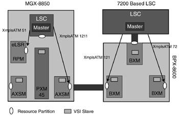
In a typical application, you can tunnel an LDP session as well as the created LVCs in a Permanent Virtual Path (PVP). To re-emphasize the concept, in the LSR, you partition resources (for example, VPI range) in the controlled switch, and the LSC learns about those resources (by means of VSI) and uses them. In contrast, in the eLSR, the switch has no resources to partition, and the MPLS application has no VSI messaging; consequently, you need to specify in the RPM acting as the eLSR the VPI to use as a tunnel. MPLS Implementation SummaryAs a summary, an MGX-8850 PXM-45-based LSR connected to a BPX-8600 LSR running MPLS looks like Figure 3-23. Figure 3-23. BPX-8600 and MGX-8850 LSRs
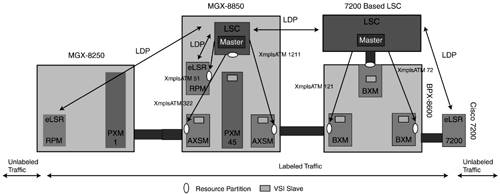
In the MGX-8850, the PXM-45 acts as a slave for connection setups/commits for the RPM-PR acting as the eLSR. From the LSC perspective, those resource partitions assigned to it are seen as XmplsATM interfaces. Finally, you can add eLSRs at both ends to complete the picture, as shown in Figure 3-24. Figure 3-24. BPX-8600 and MGX-8850 LSRs and MGX-8250 and Cisco 7200 eLSRs
The PXM-1-based MGX-8250 can act only as an eLSR. The labeled traffic and unlabeled traffic references do not consider the eLSR in the RPM-PR card in the MGX 8850. |

EAN: 2147483647
Pages: 149