Access Layer Switching
| The role of the access switch is to physically aggregate user ports and switch user traffic both locally and to the distribution layer. Figure 11-1 shows a wiring closet deployment. User-facing ports connect to end stations, such as servers, laptops, or phones, at rates of 10 Mbps, 100 Mbps, or 1000 Mbps. The uplinks are currently designed to operate at 1 Gbps, 10 Gbps, or as aggregated bundles of 1 Gbps, such as four 1-Gbps ports using EtherChannel. Access switches can be logically stacked into a group that can be managed as a single entity with one IP address and one configuration file. Stacked switches provide local switching capability across disparate physical chassis and can appear from the outside to function as a single device. Stacking implementation varies wildly, from highly sophisticated redundant ring-based interconnects to simple point-to-point connections cascaded from switch to switch. Figure 11-1. Access Layer Switching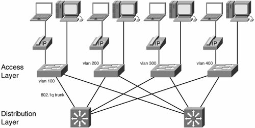 In the classic campus design, each wiring closet switch has redundant connections to two different distribution switches and runs the Spanning Tree Protocol to select forwarding paths and provide redundancy in the Layer 2 domain. There are well-documented improvements to the original 802.1D standard, such as Per VLAN Spanning Tree Plus (PVST+) and Rapid Spanning Tree Protocol (RSTP), to cite just two examples. These have been incorporated into the IEEE specification as the 802.1D-2004 standard. We greatly encourage network administrators to make sure they use current Spanning-Tree implementations and enable PortFast and UplinkFast on access and trunk ports, respectively. In addition, user-facing ports should be configured with the bridge protocol data unit (BPDU) Guard feature to prevent users from accidentally or intentionally adding a switch to the network (and playing havoc with spanning tree). Figure 11-1 shows another recommended design practice, with one VLAN for each access switch. Spanning tree will select a trunk link to one of the distribution switches, with the other available for redundancy. It is possible to load balance traffic across the Layer 2 trunks. In the event that the network runs Voice over IP, the switches will also have a voice VLAN (also called the auxiliary VLAN). In this scenario, the wiring closet trunk interfaces will always carry at least two VLANs: a native VLAN for data and the auxiliary VLAN for voice. VLANs limit broadcast domains; therefore, Cisco recommends no more than 512 devices in a wiring closet VLAN, which translates to 2 Class C IP subnets. Irrespective of the size, because of the recommendation of one VLAN per closet, there must also be least one different IP subnet for each closet, too. The voice VLAN is on a different subnet than the data endpoints, and it is recommended to use an RFC 1918 subnet address for voice end systems. This is both for reasons of security and address management. Because data end stations might need to use a public IP address, you can conserve those addresses by using private ones for the voice VLAN. Also, a separate VLAN offers some protection from attacks or viruses originated on PCs. There is obviously more flexibility in smaller deployments than these hard numbers suggest. Most access layer switches are pure Layer 2 affairs, with a single IP address for management purposes. However, in some cases it can make sense to deploy Layer 3 up to the edge of the network. In these cases, the wiring closet switches must run a routing protocolEnhanced Interior Gateway Routing Protocol (EIGRP) or Open Shortest Path First (OSPF)instead of the Spanning Tree Protocol on the uplinks. At the beginning of this section, we mentioned stacking as a common feature on wiring closet switches. Be careful that you do not design out the redundancy from the access layer by tying the switches together with a half-duplex stack link. All the careful engineering of spanning tree, VLANs, and fast reconvergence cannot help if there is a single path of failure for the access switches in a closet. In addition, be careful that stacks do not add excessive latency to the end-to-end voice path. At high speed, this is unlikely, but congested switches can start queuing, and there is a well-defined time budget (150ms) available for voice packets to reach their destination. Distribution layer switches have sophisticated hardware, and there is a lot to be said for using it. Access switches can deliver electrical power to end stations. This is useful to power wireless access points, small video cameras (for surveillance), and IP phones on an Ethernet network. Wiring closet switches sometimes have an auto-detection feature to recognize the type of endpoint connected to a port (Cisco devices use the Cisco Discovery Protocol [CDP] for this and auto-detect Cisco IP phones), which in turn allows them to send the correct amount of power over category 5 cable. The power budget of switches is not engineered to run all the ports at the highest power levels. End devices can negotiate predetermined, standardized power levels with the switch. Power over Ethernet is standardized as IEEE 802.3af. The access layer is an important component in enforcing overall network security policy, especially the prevention of Layer 2 and Layer 3 spoofing. For example, the access switch should limit hosts to transmit only IP packets using the address allocated to them by DHCP. On a Cisco switch, you enable DHCP snooping (ip dhcp snooping command) to build a table of which Layer 3 / Layer 2 address combinations are allowed on which ports, and enforce the mapping using IP source guard (ip verify source command). IP source guard prevents a host from spoofing its IP address. When the switch has a trusted MAC-IP address database, such as the one provided by DHCP snooping, it can also prevent gratuitous Address Resolution Protocol (ARP). Using the dynamic ARP inspection feature, a switch looks at ARP replies generated by end stations and drops packets that purport to be from an IP address other than the one granted by DHCP on that port. Port security, which we cover more extensively later, enables the administrator to protect the switch's content-addressable memory (CAM) table and limit the number of hosts allowed per port. Private VLANs are another security feature that prevents user ports from communicating directly with each other. End-stations can send traffic only to a selected trunk port. This is not applicable in the typical office environment (no matter how little you like your neighbor), but proves useful in shared public-space deployments such as airports, hotels, or universities, where most users only want to connect to servers or to the Internet. Private VLANs also prove useful between servers for infection containment. The need to transport voice was the reason for quality of service (QoS) deployment in the access layer. To support VoIP, a switch, at the very least, must be able to differentiate between voice and data packets and mark each accordingly for appropriate treatment in the core. Chapter 10, "Quality of Service in a Virtualized Environment," discussed the QoS policy markings that the access layer must support. The access switch should also be able to rate limit incoming traffic on trunk ports to accommodate interface speed mismatches and traffic bursts. On the user-facing ports, per-class marking and rate limiting are powerful security features. Excess burst traffic of the sort generated by viruses and worms can be marked and dropped aggressively to protect network bandwidth from being overrun. The access switch must also provide class-based low-latency queuing to guarantee timely voice packet delivery in the case that the trunk becomes congested. The more advanced QoS features are expensive to implement in hardware, so they tend to appear correctly implemented only on higher-end products, despite some elaborate data-sheet claims. The following list summarizes several of the more important access layer features:
QoS underlines the access layer's role as the perimeter of the network trust boundary. In Cisco-recommended designs, policy should be applied and enforced as early as possible. Not only should the access layer discard noncompliant traffic, it should also prevent unwanted traffic from being put on the network in the first place. Sometimes, authorized users send unauthorized traffic, which can be dealt with by using a combination of QoS and ACLs, but those are coarse-grained tools when it comes to detecting unwanted or untrusted users in the first place. This brings us to the relatively recent requirement for access switches to be able to identify users and to authenticate them before accepting their data. The next section of this chapter discusses authentication and authorization, which are the two components of access layer functionality that are affected by network virtualization. The reason is simply stated as follows: Virtual Network membership is an aspect of overall network policy and, therefore, must be applied and enforced at the network edge. The access layers must place users into the correct Virtual Network as part of the authentication and authorization process. That said, recognize that the access layer is already virtualized and has been for a long time! The switches use VLANs, and Ethernet frames are encapsulated in 802.1q as they traverse trunk links, with separate virtual networks for at least two applications (data and voice). As long as the access layer remains a Layer 2 environment, the existing mechanisms will continue to function just as before virtualization is deployed elsewhere in the enterprise network, with the possible need of supporting more VLANs on the network than before (if policy on a virtual network introduces new groups of users, there will need to be more VLANs at the access). |
EAN: 2147483647
Pages: 128