Hop to Hop
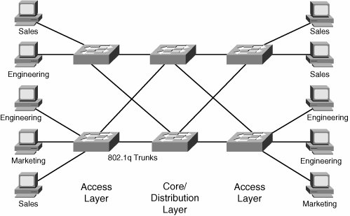
| Hop to hop (h2h) is a naive VPN architecture in which every node is a member of all virtualized networks. Consider the example of VLANs. To have complete networkwide reachability, whereby any end station can be part of any VLAN, all switches on the network must be part of all the VLANs. In terms of topology, h2h is a form of p2p network with no overlay capability. Consider the classic example of a switched enterprise network with three departments: marketing, engineering, and sales. End-user populations are physically interspersed, so, horrifying though this would be in practice for both parties, an engineer and marketing expert might sit next to each other. Site policy dictates that users are allowed to send traffic only to other members of their group. In practical terms, this means that every access switch must be able to place any of its ports into the marketing, engineering, or sales VLANs (assume VLAN membership is statically configured). In an h2h architecture, the VLANS would span across the network, and every switch would be a simple Layer 2 device running Spanning Tree Protocol (STP), as shown in Figure 5-1. Figure 5-1. Layer 2 H2H Design The complexity of this scenario relates to two factors, one of which is implementation dependent; the other is inherent to the architecture. The implementation limitation is running STP across a network. Unless the network is small, STP has well-known convergence limitations that make it a suboptimal protocol to calculate paths across large networks. It will work, but there is a better way! You could argue that STP can be enhanced (and it can be: Per VLAN Spanning Tree Plus [PVST+], Rapid Spanning Tree Protocol [RSTP, 802.1w], and so forth prove this fact). With enhancement, the architecture itself is viable. There is some truth to this argument, but this sort of design does have limitations. In our design, we are building a VPN, with a core network, which is switched Ethernet based, and customer sites, each of which has just one user. The location of sites is unpredictable and impermanent: Users are told where to sit and can be told to move (not by the networking department). The automatic response for most readers is, probably, that naive h2h designs "do not scale." Why not? In our VPN scenario, the core network is correlated to the customer groups and sites. Each switch must run three instances of STP, one for every group. If the number of groups increases, so does the load on every switch. Note that this load is on both the control and data planes. Breaking this link is one of the keys to creating scalable VPN designs. Note The term core here refers to the set of network devices that make up the shared, virtualized infrastructure over which you run private networks. Provisioning complexity is another fundamental component of scale. We can break this down into three simple questions:
The VLAN-based h2h design does well on some of these and badly on others. Most obviously, in the absence of protocol support (eg. VTP), adding a new group is painful because you must configure every device in the core network (remember, user location is unpredictable, so this means every device, not just devices that currently connect members of the new group). Adding a new site, however, is simple. A single, simple command sets the port in a new VLAN. The new user can send traffic almost instantly (if the switch uses the Cisco PortFast feature). Adding a new core switch is operationally easy, but computationally expensive because of the nature of the control-plane protocol we are using. To add a new device, just create the appropriate VLANs on the appropriate ports (or trunks) and connect them, whereupon every switch will rerun its spanning-tree calculation to compute the optimum layer path for the new topology. In real networks, VPNs are often not so private. Groups do need to communicate, either directly or to the same destination (e-mail servers, the Internet). An issue with Layer 2 h2h design is that users are locked into their VPN, so marketing, engineering, and sales cannot communicate. Although you might think this is the ultimate productivity enhancer, it would probably have detrimental long-term effects for the company in question. There are practical answers, of course, such as running applications on multihosted servers and using Network Address Translation (NAT) to access the Internet, but the network solution itself is rigid. Layer 3 H2HThe next scenario is to replace the control-plane protocol in our design and use a Layer 3 h2h solution. This time, each core node runs IP and some form of routing protocol and maintains address space virtualization using VPN routing and forwarding instances (VRFs). Note A hybrid solution is possible, with a Layer 2 access and Layer 3 distribution mapping VLANs to VRFs. The point of interest for us is how the introduction of Layer 3 addresses the scalability concerns mentioned in the previous section. As Figure 5-2 shows, the data path still uses VLANs. We are just removing end-to-end spanning tree from the network. The choice of routing protocol is determined by the usual trade-offs; in practice, the network would probably run the Open Shortest Path First (OSPF) Protocol or Enhanced Interior Gateway Routing Protocol (EIGRP). Note that perVRF support for the routing protocol implementation is a requirement for this solution. Figure 5-2. Layer 3 H2H Design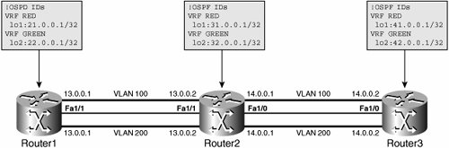 From the point of view of scale, this is the same architecture as the Layer 2 h2h design. The difference is that the control protocol is known to be robust and to work exceptionally well in large networks. What we gain in control protocol performance, we pay for in operational complexity, however. Adding a new site is still straightforward, even if there are a couple of extra instructions to put the interface into a VRF (rather than a VLAN). Each VRF needs its own dedicated path to reach neighbors. Figure 5-2 uses VLANs to connect VRFs, but any type of tunnel would work (GRE is another simple-to-use choice). However, configuring a new routed node is more involved than adding a new Ethernet switch. You must correctly configure the routing protocol, advertise the right networks in the right way, make sure you have routes for the router processor (RP) adjacencies to form, and so forth. If your network is big enough (and that does not have to be large), the added provisioning complexity is compensated for by the greater scaling characteristics of IP's control plane. No law states that you must configure a routing protocol. Static routing brings a certain set of benefits all by itself (no STP, for example) and, in a real-world design, you can constrain the provisioning complexity with an outer layer of static routing (on the access switches, for examplewhich we recommend) and routing protocols running on a set of nodes that change little (distribution and core). Adding a new user group is equally as painful for the Layer 2 scenario. Every node must be configured with the new VRF. The routing protocol must be updated with a new address family for the VRF, as discussed in Chapter 4. Despite all these limitations, consider the advantage of the h2h design:
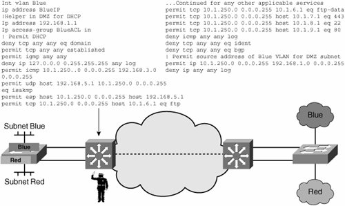
The Layer 3 h2h design also supports hierarchy well. Therefore, you do not have to build a full mesh of physical or logical links between all the CE devices (which is another way to describe the access layer). The control plane calculates the best paths no matter what topology it has to work with. This is true of the Layer 2 design, but it is just more scalable to run OSPF, for example, across a large, complex topology than it is to use STP. Finally, our Layer 3 h2h also has correlated core/user space. Increasing the number of groups increases the load on all the core devices. One suspects that there must be a better alternative. Single Address Space AlternativesAt this point, you might be somewhat frustrated by our intransigent obsession with overlapping address spaces. Although support for overlapping address spaces is a fundamental characteristic of a VPN and a generic requirement of virtualized infrastructure, it is not true that all enterprise networks have addresses that overlap across user groups. If we lift this mandate temporarily, what, if any, are the design alternatives that emerge? Within a single address space, the role of the virtualized network is simply to stop user traffic from going where it should not go. The mechanisms to do this are well known, as follows:
With the exception of MTR, neither of the two other solutions have pleasing characteristics of scale or operational simplicity. However, centralizing policy enforcement is hugely useful and is one of the major drivers for virtualizing networks. The ACL solution shown here is just insufficient, except in cases of extremely simple group membership and group topology. H2H SummaryAlthough there are definite scalability limitations, with the right design requirements and with the right control plane, h2h architectures do solve legitimate problems. They are a good fit for simple and small networks where their provisioning complexity is tolerable enough for the benefits of the design to be realized. H2h design, in the form of combined Layer 2 access and Layer 3 access distribution and core design (which we reviewed in Chapter 3) has worked extremely well in enterprise networks. Unfortunately, virtualization creates design requirements and scaling limitations that are often better solved using alternative architectures. |
EAN: 2147483647
Pages: 128