Modeling 3D Solids
| | ||
| | ||
| | ||
Well, we finally get down to where this chapter was originally headed: creating 3D solids in Flash!
In the computing world, the first example in any book or tutorial is almost always Hello, World, a program that will in one way or another print those words to the screen. In programming 3D solids, the equivalent seems to be a spinning cube. Lets not break from tradition.
Modeling a spinning cube
First of all, you need eight points to define the eight corners of the cube. These are as shown in Figure 16-14.
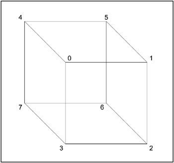
Figure 16-14: The points of a 3D cube
The points are defined like this in the code:
// front four corners points[0] = {x:-100, y:-100, z:-100}; points[1] = {x:100, y:-100, z:-100}; points[2] = {x:100, y:100, z:-100}; points[3] = {x:-100, y:100, z:-100}; // back four corners points[4] = {x:-100, y:-100, z:100}; points[5] = {x:100, y:-100, z:100}; points[6] = {x:100, y:100, z:100}; points[7] = {x:-100, y:100, z:100}; Then you need to define the triangles. Each face of the cube will consist of two triangles. There will be 12 triangles altogethertwo each for the six faces. Again, Im going to list the points for each triangle in a clockwise direction, as seen from the outer face of that triangle. It gets a little tricky, but try to rotate the cube in your mind so that the triangle youre defining is facing you, and then list the points in clockwise order from that viewpoint. For example, the front face is easy; Figure 16-15 shows the two triangles.
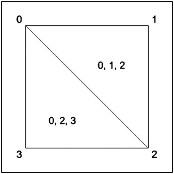
Figure 16-15: The front face of the cube
Figure 16-16 shows the top face.
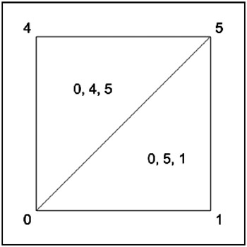
Figure 16-16: The top face of the cube
And Figure 16-17 shows the back.
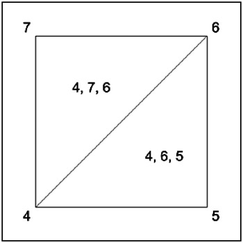
Figure 16-17: The back face of the cube
Continuing around with each face, you come up with the following triangle definitions:
// front triangles[0] = {a:0, b:1, c:2, col:0x6666cc}; triangles[1] = {a:0, b:2, c:3, col:0x6666cc}; // top triangles[2] = {a:0, b:5, c:1, col:0x66cc66}; triangles[3] = {a:0, b:4, c:5, col:0x66cc66}; //back triangles[4] = {a:4, b:6, c:5, col:0xcc6666}; triangles[5] = {a:4, b:7, c:6, col:0xcc6666}; // bottom triangles[6] = {a:3, b:2, c:6, col:0xcc66cc}; triangles[7] = {a:3, b:6, c:7, col:0xcc66cc}; // right triangles[8] = {a:1, b:5, c:6, col:0x66cccc}; triangles[9] = {a:1, b:6, c:2, col:0x66cccc}; // left triangles[10] = {a:4, b:0, c:3, col:0xcccc66}; triangles[11] = {a:4, b:3, c:7, col:0xcccc66}; Notice also that each face has a different color, as the two triangles that make up that face are the same color . Again, this clockwise orientation doesnt matter a whole lot right now, but in the next chapter, youll use this for something called backface culling . This term refers to a way of determining which surfaces are facing you and which are facing away. Youll see why this is important in a moment.
The ch16_09.fla file is exactly the same as ch16_08.fla , with these new point and triangle definitions in the init function, and one other change. In the renderTriangles function, I changed the transparency of the fill from 100 to 50.
beginFill(tri.col, 50 );
This allows you to see inside the cube and across to the opposite side. Why did I do this? Why not just have a solid cube? Well, go ahead and change 50 back to 100 and see what happens. Whoathats all messed up! You can see some of the back faces, some of the time. Other faces seem invisible all the time. Whats going on? The faces on the back of the cube (the back faces) are always being drawn. And the triangles are being drawn in the same order, based on their position in the triangles array. So the faces at the bottom of the list always draw over the faces at the top of the list, and you get bizarre, unpredictable results like this. You need to cull , or weed out and get rid of, those back faces, since you dont need to render them.
Again, backface culling will be covered in detail in the next chapter, and youll also learn how to apply some basic lighting on each surface, based on its angle. For the rest of this chapter, well just leave the transparency at 50 and live with it.
Figure 16-18 shows the finished 3D cube.
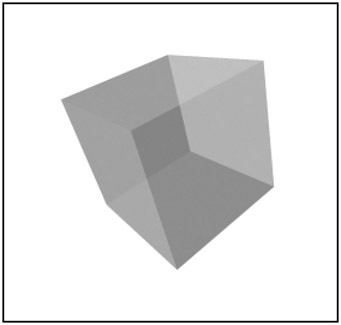
Figure 16-18: The resulting 3D cube
Modeling other shapes
Congratulations! Youve mastered the spinning cube. Now you can move on to model all kinds of shapes. Just draw them out on a piece of graph paper, mark up the points and triangles, and put them into the arrays. It often helps to draw several views of the object, rotated so you can see each face and what points make up the triangles. This section offers a few to get you started.
Pyramid
Heres the code for a 3D pyramid ( ch16_10.fla ):
points[0] = {x: 0, y:-200, z: 0}; points[1] = {x: 200, y: 200, z:-200}; points[2] = {x:-200, y: 200, z:-200}; points[3] = {x:-200, y: 200, z: 200}; points[4] = {x: 200, y: 200, z: 200}; triangles[0] = {a:0, b:1, c:2, col:0x6666cc}; triangles[1] = {a:0, b:2, c:3, col:0x66cc66}; triangles[2] = {a:0, b:3, c:4, col:0xcc6666}; triangles[3] = {a:0, b:4, c:1, col:0x66cccc}; triangles[4] = {a:1, b:3, c:2, col:0xcc66cc}; triangles[5] = {a:1, b:4, c:3, col:0xcc66cc}; Figure 16-19 shows the result.
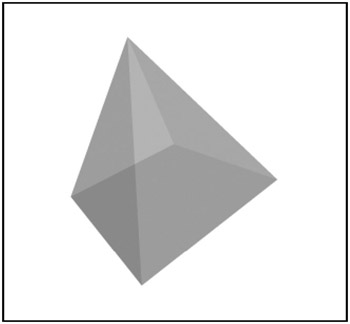
Figure 16-19: A 3D pyramid
Extruded letter A
In ch16_11.fla , I went all out and extruded the earlier letter A example. This meant copying the first 11 points, moving one set to a z of ˆ 50 and the other set to +50, then creating triangles for the second set (making sure they were still going clockwise as seen from the back), and finally making triangles to join the two sides. Tedious? You bet! But a nice effect when it was done:
points[0] = {x: -50, y:-250, z:-50}; points[1] = {x: 50, y:-250, z:-50}; points[2] = {x: 200, y: 250, z:-50}; points[3] = {x: 100, y: 250, z:-50}; points[4] = {x: 50, y: 100, z:-50}; points[5] = {x: -50, y: 100, z:-50}; points[6] = {x:-100, y: 250, z:-50}; points[7] = {x:-200, y: 250, z:-50}; points[8] = {x: 0, y:-150, z:-50}; points[9] = {x: 50, y: 0, z:-50}; points[10] = {x: -50, y: 0, z:-50}; points[11] = {x: -50, y:-250, z: 50}; points[12] = {x: 50, y:-250, z: 50}; points[13] = {x: 200, y: 250, z: 50}; points[14] = {x: 100, y: 250, z: 50}; points[15] = {x: 50, y: 100, z: 50}; points[16] = {x: -50, y: 100, z: 50}; points[17] = {x:-100, y: 250, z: 50}; points[18] = {x:-200, y: 250, z: 50}; points[19] = {x: 0, y:-150, z: 50}; points[20] = {x: 50, y: 0, z: 50}; points[21] = {x: -50, y: 0, z: 50}; triangles[0] = {a:0, b:1, c:8, col:0x6666cc}; triangles[1] = {a:1, b:9, c:8, col:0x6666cc}; triangles[2] = {a:1, b:2, c:9, col:0x6666cc}; triangles[3] = {a:2, b:4, c:9, col:0x6666cc}; triangles[4] = {a:2, b:3, c:4, col:0x6666cc}; triangles[5] = {a:4, b:5, c:9, col:0x6666cc}; triangles[6] = {a:9, b:5, c:10, col:0x6666cc}; triangles[7] = {a:5, b:6, c:7, col:0x6666cc}; triangles[8] = {a:5, b:7, c:10, col:0x6666cc}; triangles[9] = {a:0, b:10, c:7, col:0x6666cc}; triangles[10] = {a:0, b:8, c:10, col:0x6666cc}; triangles[11] = {a:11, b:19, c:12, col:0xcc6666}; triangles[12] = {a:12, b:19, c:20, col:0xcc6666}; triangles[13] = {a:12, b:20, c:13, col:0xcc6666}; triangles[14] = {a:13, b:20, c:15, col:0xcc6666}; triangles[15] = {a:13, b:15, c:14, col:0xcc6666}; triangles[16] = {a:15, b:20, c:16, col:0xcc6666}; triangles[17] = {a:20, b:21, c:16, col:0xcc6666}; triangles[18] = {a:16, b:18, c:17, col:0xcc6666}; triangles[19] = {a:16, b:21, c:18, col:0xcc6666}; triangles[20] = {a:11, b:18, c:21, col:0xcc6666}; triangles[21] = {a:11, b:21, c:19, col:0xcc6666}; triangles[22] = {a:0, b:11, c:1, col:0xcccc66}; triangles[23] = {a:11, b:12, c:1, col:0xcccc66}; triangles[24] = {a:1, b:12, c:2, col:0xcccc66}; triangles[25] = {a:12, b:13, c:2, col:0xcccc66}; triangles[26] = {a:3, b:2, c:14, col:0xcccc66}; triangles[27] = {a:2, b:13, c:14, col:0xcccc66}; triangles[28] = {a:4, b:3, c:15, col:0xcccc66}; triangles[29] = {a:3, b:14, c:15, col:0xcccc66}; triangles[30] = {a:5, b:4, c:16, col:0xcccc66}; triangles[31] = {a:4, b:15, c:16, col:0xcccc66}; triangles[32] = {a:6, b:5, c:17, col:0xcccc66}; triangles[33] = {a:5, b:16, c:17, col:0xcccc66}; triangles[34] = {a:7, b:6, c:18, col:0xcccc66}; triangles[35] = {a:6, b:17, c:18, col:0xcccc66}; triangles[36] = {a:0, b:7, c:11, col:0xcccc66}; triangles[37] = {a:7, b:18, c:11, col:0xcccc66}; triangles[38] = {a:8, b:9, c:19, col:0xcccc66}; triangles[39] = {a:9, b:20, c:19, col:0xcccc66}; triangles[40] = {a:9, b:10, c:20, col:0xcccc66}; triangles[41] = {a:10, b:21, c:20, col:0xcccc66}; triangles[42] = {a:10, b:8, c:21, col:0xcccc66}; triangles[43] = {a:8, b:19, c:21, col:0xcccc66}; Figure 16-20 shows the result.
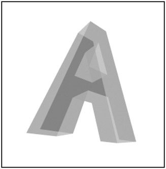
Figure 16-20: An extruded letter A
As you can see, these things build up quickly. The original, flat A had 11 triangles. Extruding it somehow quadrupled that! This code still runs pretty smoothly on a half-decent computer, but you arent going to get any massive 3D worlds with thousands of polygons in Flash. Still, you can do some pretty cool things, and the Flash Player improves in performance with each release, so who knows what the future holds?
Cylinder
One more shape example. This time Im going to show you how you can create points and triangles with some math. The only thing I changed in ch16_12.fla was the init function (and I added a numFaces variable at the top). Instead of defining points and triangles by hand, I created an algorithm to do it for me and make a cylinder. Heres that init function:
var numFaces:Number = 20; function init() { var index:Number = 0; for(var i:Number = 0;i<numFaces;i++) { var angle:Number = Math.PI * 2 / numFaces * i; var x:Number = Math.cos(angle) * 200; var y:Number = Math.sin(angle) * 200; points[index] = {x:x, y:y, z:-100}; points[index + 1] = {x:x, y:y, z:100}; index += 2; } index = 0; for(var i:Number = 0;i<numFaces-1;i++) { triangles[index] = {a:index, b:index + 3, c:index + 1, col:0x6666cc}; triangles[index+1] = {a:index, b:index + 2, c:index + 3, col:0x6666cc}; index += 2; } triangles[index] = {a:index, b:1, c:index + 1, col:0x6666cc}; triangles[index+1] = {a:index, b:0, c:1, col:0x6666cc}; } Now, I know this isnt the most lucid code, so lets go through it with some explanation and maybe a diagram or two.
Youre going to loop around in a full circle and create points at certain intervals. For each loop, you first get an angle, which is the full circle, divided by the number of faces, times the particular segment youre working on.
You use that angle, with some trigonometry you should be well used to by now, to determine the x, y point for that point on the circle. You then make two points, one with a z of ˆ 100 and one with a z of +100. When this loop is done, youll have two circles of dots, one close to you and one a bit farther away. Now you just need to connect them with triangles.
Again, you loop through for each face. This time, you create two triangles. Seen from the side, the first face looks like Figure 16-21.
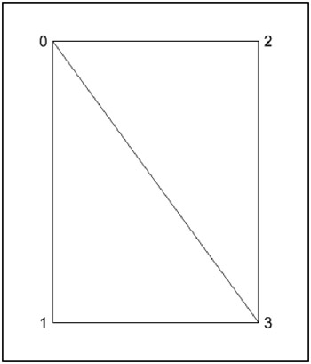
Figure 16-21: The first face of the cylinder
This makes the two triangles:
0, 3, 1 0, 2, 3
Since the index variable is 0, you can also define these like so:
index, index + 3, index + 1 index, index + 2, index + 3
which is exactly how you define the two triangles. You then increase index by 2 to handle the next face with points 2, 3, 4, and 5.
You do that up to the second-to-last face, and then connect the last one back to the first two points, 0 and 1, as shown in Figure 16-22.
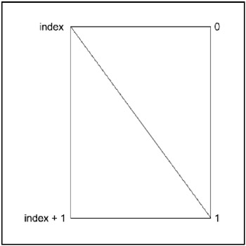
Figure 16-22: The last face of the cylinder
These wind up as follows :
index, 1, index + 1 index, 0, 1
with the result shown in Figure 16-23.
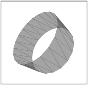
Figure 16-23: The resulting 3Dcylinder
| | ||
| | ||
| | ||
EAN: 2147483647
Pages: 137