Decoding, Mixing, and Playout
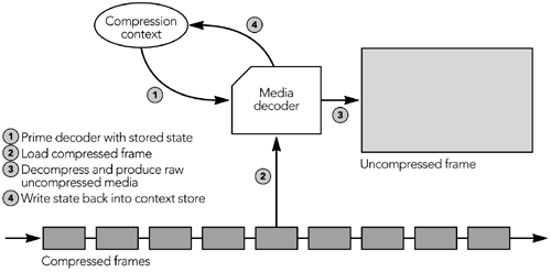
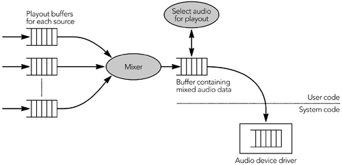
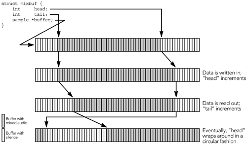
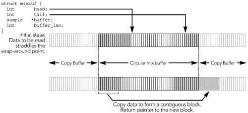
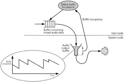
| The final stages of the playout process are to decode the compressed media, mix media streams together if there are fewer output channels than active sources, and finally play the media to the user . This section considers each stage in turn . DecodingFor each active source the application must maintain an instantiation of the media decoder, comprising the decompression routines along with state known as the compression context . The decoder may be an actual hardware device or a software function, depending on the system. It converts each compressed frame into uncompressed media data, on the basis of the data in the frame and the compression context. As each frame is decoded, the compression context for the source is updated as shown in Figure 6.19. Figure 6.19. Operation of a Media Decoder The presence of accurate state in the decompression context is fundamental to correct operation of the decoder, and codecs will produce incorrect results if the context is missing or damaged. This is most often an issue if some data packets are lost because there will be a frame that cannot be decoded. The result will be a gap in the playout where that frame should have been, but the decompression context will also be invalidated and the following frames will be corrupted. Depending on the codec, it may be possible to feed it an indication that a frame has been lost, allowing the decoder to better repair the context and reduce the damage to the media stream (for example, many speech codecs have the notion of erasure frames to signal losses). Otherwise the receiver should try to repair the context and conceal the effects of the loss, as discussed in Chapter 8, Error Concealment. Many loss concealment algorithms operate on the uncompressed media data, after decoding and before mixing and playout operation. Audio MixingMixing is the process of combining multiple media streams into one, for output. This is primarily an issue for audio applications because most systems have only a single set of speakers but multiple active sources ”for example, in a multiparty teleconference. Once audio streams have been decoded, they must be mixed together before being written to the audio device. The final stages of an audio tool will typically be structured somewhat as shown in Figure 6.20. The decoder produces uncompressed audio data on a per-source basis, written into a per-source playout buffer, and the mixer combines the results into a single buffer for playout (these steps can, of course, be combined into one if the decoder understands the mixing process). Mixing can occur at any time after the media has been decoded, and before it is due for playout. Figure 6.20. Audio Mixing The mix buffer is initially empty ”that is, full of silence ”and each participant's audio is mixed into the buffer in turn. The simplest approach to mixing is saturating addition , in which each participant's audio is added to the buffer in turn, with overflow conditions saturating at extreme values. In pseudocode, assuming 16-bit samples and mixing a new participant ( src ) into the buffer ( mix_buffer ), this becomes audio_mix(sample *mix_buffer, sample *src, int len) { int i, tmp; for(i = 0; i < len; i++) { tmp = mix_buffer[i] + src[i]; if (tmp > 32767) { tmp = 32767; } else if (tmp < -32768) { tmp = -32768; } mix_buffer[i] = tmp; } } Other algorithms are possible if higher-fidelity mixing is required. Mixing samples is a task for which SIMD processors often have instructions. For instance, the Intel MMX (Multimedia Extensions) instructions include saturating-add instructions that add four 16-bit samples at a time, and because the mixing loop no longer has the branch checks, the performance can be up to ten times faster. The actual mix buffer can be implemented as a circular buffer. The buffer is implemented as an array with start and end pointers, wrapping around to give the illusion of a continuous buffer (see Figure 6.21). Figure 6.21. Implementation of a Circular Mix Buffer A limitation of the simple circular buffer is that it cannot always make a continuous buffer available for readout. Instead, as the readout nears the wrap-around point, it will be necessary to return two blocks of mixed data: one from the end of the circular buffer, one from the beginning. The need to return two buffers can be avoided if an array of twice the required size is allocated. If the readout routine requests a block that includes the wrap-around point in the circular buffer, the mixer can copy data into the additional space and return a pointer to a continuous block of memory as shown in Figure 6.22. This requires an additional copy of the audio data, up to half the size of the circular buffer, but allows the readout to return a single contiguous buffer, simplifying code that uses the mixer. Normal operation of the circular buffer is unchanged, except for a single copy when data is being read out. Figure 6.22. Implementation of a Circular Mix Buffer with Additional Copy Buffer Audio PlayoutThe process by which audio is played to the user is typically asynchronous, allowing the system to play one frame of audio while processing the next . This capability is essential to normal operation because it allows continuous playback even though the application is busy with RTP and media processing. It also shields the application from variations in the behavior of the system, perhaps due to other applications running on that system. Asynchronous playout is especially important on general-purpose operating systems with limited support for multimedia applications. These systems are typically designed to give good average response, but often they have undesirable worst-case behavior, and typically they cannot guarantee that real-time applications are scheduled appropriately. An application can use asynchronous playout to its advantage, using the audio DMA (directory memory access) hardware to maintain continual playout. 83 As shown in Figure 6.23, an application can monitor the occupancy of the output buffer and adjust the amount it writes to the audio device according to the time since it was last scheduled, such that the buffer occupancy after each iteration is constant. Figure 6.23. Use of an Audio DMA Buffer for Continual Playout If the application detects a period of unusual scheduling latency ”perhaps due to heavy disk activity on the system ”it can preemptively increase the size of the audio DMA buffer, up to the limit imposed by the playout point. If the operating system does not allow direct monitoring of the amount of audio buffered and awaiting playout, it may be possible to derive an estimate from the amount of audio waiting to be read for the encoding side of the application. In many cases, audio playback and recording are driven from the same hardware clock, so an application can count the number of audio samples it records and use this information to derive the occupancy of the playback buffer. Careful monitoring of the audio DMA buffer can ensure continual playout in all but the most extreme environments. Video PlayoutVideo playout is largely dictated by the refresh rate of the display, which determines the maximum time between the application writing to the output buffer and the image being presented to the user. The key to smooth video playout is twofold: (1) Frames should be presented at uniform rate, and (2) changes to a frame should be avoided while the video is being rendered. The first point is a matter for the playout buffer, selecting the appropriate display time as described in the section Playout Adaptation for Video earlier in this chapter. The second point relates to the display: Frames are not presented instantaneously; instead they are drawn in a series of scan lines, left to right, top to bottom. This serial presentation allows the possibility that the application will be able to change a frame while it is being displayed, causing a glitch in the output. Double buffering can solve this problem, one buffer being used to compose a frame while the second buffer is being displayed. The two buffers are switched between frames, synchronized with the interframe gap. The means by which double buffering is achieved is system dependent but usually part of the video display API. |
EAN: 2147483647
Pages: 108