Overview of an RTP Implementation
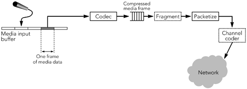
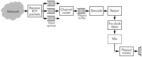
| As Figure 1.1 shows, the core of any system for delivery of real-time audio/video over IP is RTP: It provides the common media transport layer, independent of the signaling protocol and application. Before we look in more detail at RTP and the design of systems using RTP, it will be useful to have an overview of the responsibilities of RTP senders and receivers in a system. Behavior of an RTP SenderA sender is responsible for capturing and transforming audiovisual data for transmission, as well as for generating RTP packets. It may also participate in error correction and congestion control by adapting the transmitted media stream in response to receiver feedback. A diagram of the sending process is shown in Figure 1.2. Figure 1.2. Block Diagram of an RTP Sender Uncompressed media data ”audio or video ”is captured into a buffer, from which compressed frames are produced. Frames may be encoded in several ways depending on the compression algorithm used, and encoded frames may depend on both earlier and later data. Compressed frames are loaded into RTP packets, ready for sending. If frames are large, they may be fragmented into several RTP packets; if they are small, several frames may be bundled into a single RTP packet. Depending on the error correction scheme in use, a channel coder may be used to generate error correction packets or to reorder packets before transmission. After the RTP packets have been sent, the buffered media data corresponding to those packets is eventually freed. The sender must not discard data that might be needed for error correction or for the encoding process. This requirement may mean that the sender must buffer data for some time after the corresponding packets have been sent, depending on the codec and error correction scheme used. The sender is responsible for generating periodic status reports for the media streams it is generating, including those required for lip synchronization. It also receives reception quality feedback from other participants and may use that information to adapt its transmission. Behavior of an RTP ReceiverA receiver is responsible for collecting RTP packets from the network, correcting any losses, recovering the timing, decompressing the media, and presenting the result to the user . It also sends reception quality feedback, allowing the sender to adapt the transmission to the receiver, and it maintains a database of participants in the session. A possible block diagram for the receiving process is shown in Figure 1.3; implementations sometimes perform the operations in a different order depending on their needs. Figure 1.3. Block Diagram of an RTP Receiver The first step of the receive process is to collect packets from the network, validate them for correctness, and insert them into a sender-specific input queue. Packets are collected from the input queue and passed to an optional channel-coding routine to correct for loss. Following the channel coder, packets are inserted into a source-specific playout buffer. The playout buffer is ordered by timestamp, and the process of inserting packets into the buffer corrects any reordering induced during transport. Packets remain in the playout buffer until complete frames have been received, and they are additionally buffered to remove any variation in interpacket timing caused by the network. Calculation of the amount of delay to add is one of the most critical aspects in the design of an RTP implementation. Each packet is tagged with the desired playout time for the corresponding frame. After their playout time is reached, packets are grouped to form complete frames, and any damaged or missing frames are repaired. Following any necessary repairs , frames are decoded (depending on the codec used, it may be necessary to decode the media before missing frames can be repaired). At this point there may be observable differences in the nominal clock rates of the sender and receiver. Such differences manifest themselves as drift in the value of the RTP media clock relative to the playout clock. The receiver must compensate for this clock skew to avoid gaps in the playout. Finally, the media data is played out to the user. Depending on the media format and output device, it may be possible to play each stream individually ”for example, presenting several video streams, each in its own window. Alternatively, it may be necessary to mix the media from all sources into a single stream for playout ”for example, combining several audio sources for playout via a single set of speakers . As is evident from this brief overview, the operation of an RTP receiver is complex, and it is somewhat more involved than the operation of a sender. This increased complexity is largely due to the variability of IP networks: Much of the complexity comes from the need to compensate for packet loss, and to recover the timing of a stream affected by jitter. |
EAN: 2147483647
Pages: 108

