3.4 Second-Generation Mobile Networks
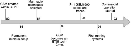
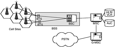
| Second-generation mobile networks are a step up in technology evolution. 2G networks, as they are commonly refered to, are digital networks. There are several 2G technologies that have been deployed across the world. The most widespread deployment is, of course, the TDMA-based GSM system and the CDMA-based IS-95 system. Other 2G technologies that have been deployed include DECT (Digital European Cordless Telephone), IS-136, and the PDC-based personal handyphone system (PHS) in Japan. The following sections will take a closer look at the GSM and CDMA networks and technology. 3.4.1 GSM (Global System for Mobile Communication)GSM is a TDMA-based wireless communications system. Work on the GSM specifications started in the 1980s in Europe as a result of the capacity limits being experienced by analog networks such as NMT. The GSM 900 system uses two 25-MHz bands for the uplink and downlink, and within this spectrum 200-KHz channels are allocated. The uplink and downlink are separated by a 45-MHz spacing. GSM 1800 uses two 75-MHz bands for the uplink and downlink. Again 200-KHz channels are allocated within those bands and are separated by a 95-MHz spacing. The 1900-MHz systems use two 60-MHz bands for the uplink and downlink using 200-MHz channels within those bands and separated by 80-MHz spacing. STANDARDSEurope felt the need for a common mobile telephony standard since different countries had differing analog networks, and as a result roaming of subscribers between these networks was not possible. CEPT (Conference European des Postes et Telecommunications) is a standardization arena in Europe. A new group called GSM (Groupe Special Mobile) was formed within CEPT in 1982 whose task was to specify a unique radio communication system for Europe at 900 MHz. The timeline in Figure 3-6 shows the progress and implementation of the GSM standard. Figure 3-6. GSM standards timeline. GSM TOPOLOGYThe topology and network architecture of GSM is shown in Figure 3-7. Figure 3-7. GSM network architecture. The mobile station (MS) is the terminal (phone, PDA mobile unit) provided to the subscriber. It is essentially a GSM two-way radio that conforms to the air interface specifications. The base station subsystem is functionally subdivided into the base station controller (BSC) and the base transceiver station (BTS). A single BSC normally controls a large number of BTSs. BTSs contain the radio equipment and are connected to cell site antennas. The BTS is essentially a layer two bridge if viewed from a high-level perspective. It provides an entry point for the subscribers who are present in the cell, allowing them to make or receive calls. Some of the base station functions are radio transmission in GSM format, use of frequency hopping techniques, coding and decoding of radio channels, and measurement of quality and received power on traffic channels. The BSC is a much more complex system. It is responsible for managing the radio resources in the network as well as control handovers. So the BSC has functionality of mobility management, radio resource management, call control, management of intercell handovers, and other housekeeping tasks . The mobile switching center (MSC) is the centrallized controller of the network. The MSC is a switch that provides call control capability. It also interfaces to the PSTN. An MSC that interfaces to the PSTN is called a gateway MSC (GMSC). The MSC also is responsible for tracking the user as he or she moves between networks. So it plays a role in mobility management as well. GSM uses two databases, called the home location register (HLR) and the visitor location register (VLR). The HLR contains the subscriber's profile information (which is static) as well as the current location of the subscriber (i.e., it knows the reachability information of the subscriber). The VLR stores the current location or point of attachment to the network and the state of the mobile terminal. For mobile terminated calls, the HLR is the initial signaling contact point in the mobile network, whereas the VLR is the initial signaling contact when the call originates from the mobile. The authentication center (AuC) is a database that stores confidential information, such as keys associated with valid subscribers. The AuC is responsible for authenticating a subscriber. When subscribers attach to the network, the network performs an authentication procedure for the subscriber. The keys associated with the subscriber are utilized in conconjunction with an algorithm to validate the authenticity. The secret key associated with the subscriber is stored on the subscriber identity module (SIM). INTERFACESFour main interfaces are defined in GSM networks:
The Um interface uses a combination of FDMA and TDMA access techniques. One hundred twenty-four full-duplex channel pairs are defined that operate with different carrier frequencies. Each of these FDM channels uses TDMA slots. The Abis interface connects the BTSs with a BSC. The Abis interface has normally been implemented as a proprietary interface. The physical layer is defined by a 2-Mbps PCM link, and the datalink uses LAPD. The A interface is an open interface that connects the radio access network (RAN) to the core network. The A interface links multiple BSCs to an MSC. It is the open nature of this interface that makes it possible to connect equipment made by different vendors . The A interface functions include call control and mobility signaling. THE SUBSCRIBER IDENTITY MODULEThe SIM is a personalized part of the mobile station and operates along with a memory card. The SIM identifies the subscriber. The mobile station is simply a piece of radio equipment and becomes associated with a subscriber only as a result of the SIM being inserted into the terminal. The SIM provides the security needs of the operator and the subscriber. With the SIM concept, a subscriber is not tied to any specific mobile terminal. A subscriber can use different terminals. As far as the network operator is concerned , a subscriber is identified by the SIM. It identifies the account owner and can be modified or subscription options changed. The key functionalities afforded by SIM are subscriber authentication, secure location for secret keys at the subscriber end, processing capability for executing the authentication, and ciphering algorithms. MOBILE APPLICATION PARTMAP is a protocol used in GSM core networks on various interfaces. MAP can be denoted as MAP-x, where x can determines the interface. The interfaces where MAP is used are shown in Table 3-1. Functionalities associated with each of these interfaces are defined in the specifications for MAP in GSM 09.02. Table 3-1. MAP Interfaces
3.4.2 CDMA IS-95CDMA is a relatively new technology in the mobile cellular industry. Commercial networks were first deployed in the mid-1990s. However, they are growing rapidly and they account for about 25% of the wireless networks globally. The CDMA standard referred to as IS-95 is specified by TIA/EIA. SPREAD SPECTRUMThe wireless spectrum is a scarce resource, with tight regulations in terms of usage and power radiated along with licenses required to operate. This is true for most of the wireless systems in place. Interference is an issue that wireless networks must contend with. Spread spectrum is one of the techniques employed that inherently is less sensitive to interference. Spread spectrum techniques typically use more bandwidth than necessary to transmit and receive bits. Spread spectrum techniques inherently offer more privacy than narrowband techniques, as they are more difficult to intercept or spy on. They use a code, which is known only to the transmitter and the receiver. Spread spectrum techniques can also coexist with other technologies as the transmitter and receiver can obtain information as long as they are decoding with the same code.
There are two popular spread spectrum techniques. The first is frequency hopping spread spectrum (FHSS), where the transmitter and the receiver hop in a predetermined sequence through a wide band of frequencies. The second technique is direct sequence spread spectrum (DSSS), a mechanism in which data bits are transformed by codes, which in turn occupy a wide band of frequencies. This technique is already in use in public wireless networks such as IS-95 (or CDMA, as it is popularly known). DSSS is a technique wherein the carrier is modulated by a digital code in which the code bit rate is much larger than the information signal bit rate. The DSSS system is a wideband system in which the entire bandwidth of the system is available to the user. The user data is spread using a spreading signal refered to as the code signal. The code signal or the spreading signal has a much higher data rate than the user data rates; for example, the 1.2288 MCPS in CDMA vs. user data rates that are much lower. At the receiving end, despreading is accomplished by the cross corelation of the signal with a synchronized replica of the same signal used to spread the data. In CDMA systems pseduorandom noise (PN) sequences are used to spread the bandwidth and distinguish among various users' signals. PN sequences, as the name suggests, are not random but rather deterministic. ARCHITECTURE AND CHANNELSThe CDMA architecture is based on the reference model from the cellular standards group TR-45. Structure of the standards organization is discussed in Chapter 16. The main elements of the reference architecture are as follows :
IS-95 channels can be segmented into physical channels and logical channels:
INTERFACESIS-95 uses the following interfaces:
IS-41IS-41 is standardized by the Telecommunications Industry Association (TIA). Revision C is the latest version of the protocol and is called IS-41C. IS-41 is the core networking protocol that supports mobility, authentication, and roaming. IS-41 allows network equipment to be multivendor. Since the equipment has to conform to the standard interface, it is possible to have an environment wherein MSCs are from vendor A and the BSC/radio network is from vendor B. IS-41C is an application-layer protocol. IS-41 normally is operated over SS7 networks, which provide the reliability required for signaling. Roaming between networks that use GSM MAP and IS-41 requires the use of gateway functions that convert messages from one protocol to another. Such gateways can be considered protocol translators. 3.4.3 GPRS (2.5G Network)General Packet Radio Service (GPRS) is an enhancement to GSM networks with support for packet radio. GPRS overlays a packet-based air interface on the existing circuit switched network. It also introduces a packet core aspect primarily for data applications. Packet switching allows radio resources to be shared efficiently by a large number of users since radio resources are allocated if there are data to send or receive. GPRS network architecture as well as the enhancements to the air interface are covered in Chapter 8. |
EAN: 2147483647
Pages: 164

