Chapter 4 - Cisco Group Management Protocol

Chapter 4: Cisco Group Management Protocol  
  Overview  
  The Cisco Group Management Protocol (CGMP) is a proprietary layer 2 protocol that is used between Cisco routers and switches to limit multicast traffic on a virtual LAN (VLAN). CGMP was developed to address the problem illustrated in Figures 4-1 and 4-2.  
   
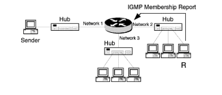
  Figure 4-1: At least one IGMP-registered receiver is required for a router to forward multicast traffic.  
   
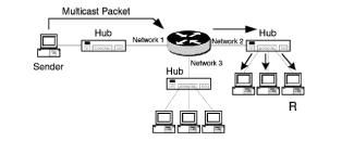
  Figure 4-2: Multicast traffic is received by all hosts on a shared hub network.  
  In Figure 4-1, the network consists of a router and three ethernet network segments. Each segment contains an ethernet hub or repeater, and a packet transmitted by the router onto one of the segments is received by every host on the segment. Assume a host on network 2 wishes to receive the multicast traffic from the source on network 1. The host on network 2 sends an IGMP Join message to the router, and the router installs state for network 2, indicating that there is at least one receiver for traffic from the indicated multicast group.  
  Remember from Chapter 3, Internet Group Management Protocol, that the router does not need to know how many receivers are on a network, only that there is at least one receiver. Network 3 has no receivers for the multicast group, so the router does not forward multicast traffic onto network 3. When the sender on network 1 transmits a multicast packet, the router forwards the traffic onto network 2, but not onto network 3. The hub on network 2 sends a copy of the packet and all subsequent packets to all hosts attached to the hub. The hosts that do not want to receive the multicast traffic must process the frame in order to determine that the frame was not intended for them.  
  Obviously, this is not an ideal situation. The ideal situation is to limit the multicast traffic not only to networks that have receivers, but also to limit the traffic to receivers on a network that want to receive it.  
  Layer-three multicast routing protocols are used to limit multicast traffic to networks that have receivers which have indicated their desire to receive the traffic. Later chapters cover layer three multicast routing protocols and their implementation.  
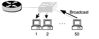
  In order to remedy the situation depicted in Figure 4-2, we will replace the hub with an ethernet switch. Assume we have an ethernet switch with 50 attached users and that virtual LANs are not being implemented. Without VLANs, every host is on the same IP subnet, and broadcast traffic from one host is flooded to all hosts on the switch (see Figure 4-3).  
   
  Figure 4-3: Without VLANs, broadcast traffic is forwarded to all hosts.  
  The situation in Figure 4-3 can be improved by reducing the size of the broadcast domain using VLANs. A VLAN is comprised of hosts in a common IP subnet. For example, if we want to reduce the size of the broadcast domains in Figure 4-3 from 50 to 25 hosts, we would need two VLANs or two logical IP subnets (LIS). Figure 4-4 contains a network where we can accomplish the same broadcast domain size reduction using two switches and no VLANs. Whenever you have more than one LIS, you need a router for intersubnet traffic.  
   
  Figure 4-4: Reducing broadcast domain size using multiple switches  
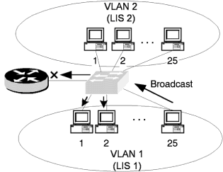
  When the broadcast frame reaches the router, it will not be propagated to LIS 1 because routers do not forward broadcast traffic.  
  The network in Figure 4-4 can be implemented using one switch and two VLANs (see Figure 4-5). Each port on the switch is assigned to either VLAN 1 or VLAN 2 and the router has two logical interfaces configured on one physical interface.  
   
  Figure 4-5: Reducing broadcast domain size using VLANs  
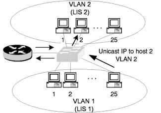
  Broadcast traffic from host 25 on VLAN 1 is only forwarded to other hosts on VLAN 1; hosts on VLAN 2 do not receive the broadcast traffic, and inter-VLAN unicast IP traffic must go to the router. In Figure 4-6, host 25 on VLAN 1 is sending unicast IP traffic to host 2 on VLAN 2. The sequence of events to accomplish this are as follows:  
   
  Figure 4-6: Sending inter-VLAN traffic  
  1.   Host 25 on VLAN 1 wants to send traffic to host 2 on VLAN 2. The destination address is on a different IP subnet, so host 25 sends the packet to the default gateway, which is the router.  
  2.   The router examines the destination address and determines the traffic is for VLAN 2, so the packet is sent back to the switch.  
  3.   The switch examines the destination MAC address and forwards the packet to host 2 on VLAN 2.  
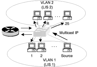
  The broadcast problem has been solved, but what about the multicast traffic? Have we improved the situation by replacing the shared hub with an ethernet switch? In Figure 4-7, one of the hosts on VLAN 1 is now a multicast sender and one host from VLAN 2 has joined the multicast group using IGMP. What will happen when the source sends a multicast packet?  
   
  Figure 4-7: Forwarding of multicast traffic on VLANs  
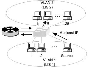
  Everyone will receive the multicast packet! Wait a minute, this is worse than the broadcast traffic. At least VLAN 2 did not receive the broadcast traffic from VLAN 1. The problem is that the switch (at least for now) treats multicast traffic like it was broadcast traffic, but the router does not. Therefore, the multicast traffic on VLAN 1 is forwarded to all hosts on VLAN 1 and the router. The router has state for the multicast group on VLAN 2 because there is a receiver on VLAN 2. The router forwards the multicast traffic to VLAN2, which treats the traffic as a broadcast and forwards it to every host on the VLAN. Looks like we need another protocol. And that protocol should cause multicast traffic to be forwarded as shown in Figure 4-8.  
   
  Figure 4-8: The ideal multicast traffic forwarding scenario  
  One method to overcome the multicast problem on switches is to manually configure the ports on the switch to receive multicast traffic. The content addressable memory (CAM) table on the switch contains a mapping of ethernet addresses to ports that the switch uses to forward traffic. A port can have multiple mappings because a hub can be tied to a switch port and multiple hosts with different ethernet addresses would depend on the port for traffic. Assume a host connected to switch port 1/4  wishes to receive traffic from the multicast group 224.65.10.154. The ethernet multicast address corresponding to this group is 01:00:5E:41:0A:9A (refer to Chapter 5) and we could put the mapping in the CAM table using the command  
  set cam permanent 01-00-5E-41-0A-9A 1/4  
  When multicast traffic arrives at the switch for group 224.65.10.154, the traffic would only be sent out through port 1/4 . What other multicast groups would have their traffic sent on only port 1/4 ? Remember that 32 different multicast groups map to the same multicast ethernet address (see Table 4-1). If traffic arrives from any one of those 32 groups, then it is sent only on port 1/4 .  
  Table 4-1: Class D multicast IP addresses that map to the multicast ethernet address 01:00:5E:41:0A:9A  
 
 
  224.65.10.154  
225.65.10.154  
 
226.65.10.154  
 
227.65.10.154  
 
  228.65.10.154  
229.65.10.154  
 
230.65.10.154  
 
231.65.10.154  
 
  232.65.10.154  
233.65.10.154  
 
234.65.10.154  
 
235.65.10.154  
 
  236.65.10.154  
237.65.10.154  
 
238.65.10.154  
 
239.65.10.154  
 
  224.193.10.154  
225.193.10.154  
 
226.193.10.154  
 
227.193.10.154  
 
  228.193.10.154  
229.193.10.154  
 
230.193.10.154  
 
231.193.10.154  
 
  232.193.10.154  
233.193.10.154  
 
234.193.10.154  
 
235.193.10.154  
 
  236.193.10.154  
237.193.10.154  
 
238.193.10.154  
 
239.193.10.154  


  Traffic for any multicast address not in the CAM table would be flooded to every port in the VLAN. This seems to be a solution to our problem. All we need to do every time a user wants to receive multicast traffic is to just add an entry to the CAM table (after we convert the IP multicast address to an ethernet multicast address). Whenever the user wants to leave the group, we just simply delete the entry from the CAM table using  
  no set cam permanent 01-00-5E-41-0A-9A 1/4  
  What could be easier? Hopefully you can see that this would be an administrative nightmare. Assuming you have hundreds or even thousands of users and only a fraction of them receive multicast traffic, this would turn into a full-time and rather boring job, but again this is not the ideal situation. Even though it achieves what we wanted, the solution is not dynamic and requires too much intervention.  
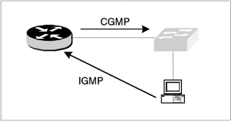
  To achieve the ideal multicast forwarding scenario, we need a protocol based on a layer two, or ethernet addresses, and one that is dynamic. And it should come as no surprise that this protocol is the CGMP. One of the main concerns when CGMP was designed was that no modifications should need to be made to existing multicast protocols on either hosts or routers. Therefore, CGMP must add additional functionality without altering the operation of IGMP or any of the layer three multicast routing protocols. The relationship between IGMP, CGMP, routers, and switches is shown in Figure 4-9.  
   
  Figure 4-9: Logical relationship between IGMP and CGMP  
  In Figure 4-9, it looks as if the host is sending the IGMP packets directly to the router and bypassing the switch. This is a logical diagram and, of course, the IGMP packet must pass through the switch. The diagram shows that IGMP is a protocol used between hosts and routers, and CGMP is the protocol used between routers and switches. The fundamental operation when using IGMP and CGMP is as follows:  
  1.   A host sends an IGMP Join to the router for a particular IP multicast group.  
  2.   The router, if CGMP is enabled, sends a message to the switch containing the unicast ethernet address of the host and the multicast ethernet address of the group the host is joining.  
  3.   The switch, if CGMP is enabled, installs the entry in the CAM table.  
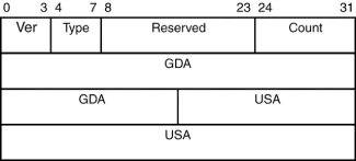
  The format of a CGMP packet is given in Figure 4 10.  
   
  Figure 4-10: CGMP packet format  
  Ver  
  CGMP version number = 1  
 
  Type  
  0 = Join, 1 = Leave  
 
  Reserved  
  Set to 0 and ignored  
 
  Count  
  Number of GDA/USA pairs in the message  
 
  GDA  
  Six-byte multicast group destination ethernet address  
 
  USA  
  Six-byte unicast source address, which is the address of the host  
 
  CGMP must be enabled on the switch and the router using the commands listed below. On the router interface connected to the switch use  
  ip cgmp  
  and on the switch use  
  set cgmp enable  
  Example  
  Enable cgmp on router interface ethernet 0  
  interface ethernet 0  
  ip cgmp  
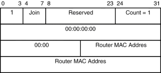
  How does the switch know to which port the router is connected? The router sends a CGMP Join message to the switch (if CGMP is enabled on the router interface) with the GDA set to zero and the USA set to the MAC address of the router port (see Figure 4-11).  
   
  Figure 4-11: CGMP Join message from a router to a switch  
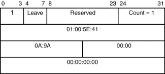
  When all the receivers for a particular multicast group leave the group, the router deletes state for the group on the interface and sends a CGMP leave message for the group to the switch. The Group Leave message contains the multicast MAC address for the group and the USA field is zero. An example CGMP Group Leave message is shown in Figure 4-12 for multicast group 224.65.10.154.  
   
  Figure 4-12: Router CGMP Leave message from a router to a switch for a particular multicast group (224.65.10.154)  
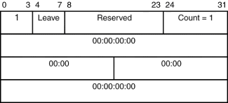
  Upon receipt of the Group Leave message, the switch deletes all entries for the multicast group from the CAM table. What happens to multicast traffic for a group that has had all CAM entries deleted from the switch? The switch floods all packets from this group to every host in the VLAN. If all receivers for all groups no longer wish to receive multicast traffic, the router sends a CGMP Leave message with both the GDA and USA fields set to zero, as shown in Figure 4-13. All multicast groups are deleted from the CAM table and all multicast packets are flooded to all hosts in the VLAN. This may seem like a problem, but if the multicast traffic does not originate from a source connected to the switch but from a source that goes through the router, then this is not a problem.  
   
  Figure 4-13: Router CGMP Leave message from a router to a switch for all multicast groups  
  If no receivers are on the switch, then the multicast routing protocols prevent the traffic from reaching the switch. Well, sometimes. As we shall see, some of the multicast routing protocols periodically flood traffic on all router interfaces, even if no receivers are present. When this occurs, the switch floods the multicast traffic on all ports.  
  CGMP messages are layer two messages and are sent to the ethernet address 01:00:0C:DD:DD:DD.
Monitoring CGMP  
  The operation of CGMP is easily verified by using debug and show commands on the router and switch. The network we will use to demonstrate the operation of CGMP is shown in Figure 4-14. The router will begin the CGMP process by sending a Join to the switch.  
   
  Figure 4-14: Host IGMP messages pass through the switch to the router.  
  Router#debug ip cgmp  
  07:59:15: CGMP: Sending self Join on Ethernet0  
  07:59:15: GDA 0000.0000.0000, USA 0010.7b3a.6171  
  08:00:15: CGMP: Sending self Join on Ethernet0  
  08:00:15: GDA 0000.0000.0000, USA 0010.7b3a.6171  
  Initially, the host sends an IGMP Group Membership Report to the router. To view this, execute the command debug ip igmp on the router:  
  router#debug ip igmp  
  09:04:55: IGMP: Received v2 report from 172.16.1.1 (Ethernet0) for 224.65.10.154.  
  To verify that the router has created an entry for the group, use the show ip igmp group command.  
  router#show ip igmp group  
  IGMP Connected Group Membership  
  Group Address  
Interface  
 
Uptime  
 
Expires  
 
Last Reporter  
 
  224.65.10.154  
Ethernet0  
 
00:00:12  
 
00:02:48  
 
172.16.1.1  
 
  The router then sends a CGMP Join to the switch (refer to Figure 4-15), which can be monitored using both the IGMP and CGMP debug commands.  
   
  Figure 4-15: After receiving an IGMP Report from the host, the router informs the switch with a CGMP Join message.  
  Router#debug ip igmp  
  02:11:18: CGMP: Received IGMP Report on Ethernet0 from 172.16.1.1 for 224.65.10.154.  
  02:11:19: CGMP: Sending Join on Ethernet0  
  GDA 0100.5E41.0A9A, USA 0010.7b3a.6171  
  When switch B receives the CGMP Join message from the router, a static CAM entry is created for the host.  
  switch (enable) show cam dynamic  
  VLAN  
  Dest MAC/Route Des  
 
  Destination Ports or VCs  
 
  1  
  0010.7b3a.6171  
 
  3/1  
 
  B (enable) show cam static  
  VLAN  
  Dest MAC/Route Des  
 
  Destination Ports or VCs  
 
  1  
  01-00-5e-41-0a-9a  
 
  3/1  
 
  Once the static CAM entry is in the table, multicast traffic that is received by the switch for group 224.65.10.154 is sent only to port 3/1 . When the host decides to leave the group, the host sends an IGMP Leave message to the router (see Figure 4-16). Here we are assuming that the host is using IGMP version 2.  
   
  Figure 4-16: The Host IGMP Leave message triggers Membership Queries from the router.  
  When the router receives the Leave message from the host, the router sends multiple Membership Queries for the group to determine if there are any members remaining.  
  routeradebug ip igmp  
  09:04:54:IGMP: Received Leave from 172.16.1.1 (Ethernet0) for 224.65.10.154.  
  09:04:55:IGMP: Send v2 Query on Ethernet0 to 224.65.10.154.  
  09:04:56:IGMP: Send v2 Query on Ethernet0 to 224.65.10.154.  
  If there is no response to the query for the group, then the router deletes the state for the group on the interface and sends a CGMP Leave for the group to the switch.  
  routeradebug ip igmp  
  02:11:18: IGMP: Deleting 224.65.10.254 on Ethernet0  
  02:11:19: CGMP: Sending Leave on Ethernet0  
  GDA 0100.5E41.0A9A, USA 0000.0000.0000  
  What happens when the router receives an IGMP v1 Leave message? Hopefully, as you remember from Chapter 3, that there are no IGMP v1 Leave messages. If the host leaves the group, the traffic for group 224.65.10.254 continues to be forwarded to the host until the state for the group expires on the router. When the state for the group does so, a CGMP Leave message is sent to the switch, deleting the entry from the CAM table.  
  The process of leaving a group can be made more efficient if the switch can monitor IGMP Leave messages. This option is called Fast IGMPv2 Leave processing and is enabled on the switch with the command shown below.  
  switch (enable) set cgmp leave enable  
  With CGMP Leave enabled on the switch, the switch processes the IGMPv2 Leave messages and does not send them to the router. If the switch knows that other receivers for the group are on the same port or VLAN, then no action is required. If the switch knows that this is the last receiver to leave the group, then an IGMP Leave message is sent to the router. To disable this feature, use:  
  switch(enable) set cgmp leave disable
CGMP Command Summary  
  Tables 4-2 and 4-3 contain a summary of the router and switch commands pertaining to CGMP. The router command, ip cgmp proxy, will be covered in Chapter 5, Distance Vector Multicast Routing Protocol.  
  Table 4-2: Router CGMP Command Summary  
 
 
  Command  
Description  


  ip cgmp  
Enables CGMP on an interface or subinterface  
 
  ip cgmp proxy  
Enables CGMP and DVMRP proxy on an interface or subinterface  
 
  clear ip cgmp [interface]  
Clears all CGMP groups  
 
  show ip igmp interface [interface]  
Shows if CGMP is enabled on an interface  
 
  debug ip cgmp  
Debugs CGMP traffic  


  Table 4-3: Switch CGMP Command Summary  
 
 
  Command  
Description  


  set cgmp enable  
Enables CGMP on the switch  
 
  set cgmp disable  
Disables CGMP on the switch  
 
  show multicast router  
Lists the ports on the switch that are router ports  
 
  show multicast group  
Displays active groups  
 
  clear cgmp statistics  
Clears the CGMP statistics  
 
  debug ip cgmp  
Debugs CGMP traffic  


  Example  
  View the switch CGMP statistics for VLAN 2  
  switch. show cgmp statistics 2  
  CGMP enabled  
  CGMP statistics for vlan 2:  
  valid rx pkts received257  
  invalid rx pkts received0  
  valid cgmp joins received252  
  valid cgmp leaves received5  
  valid igmp leaves received0  
  valid igmp queries received0  
  igmp gs queries transmitted0  
  igmp leaves transmitted0  
  failures to add GDA to EARL0  
  topology notifications received0  
  number of packets dropped0  
  Example  
  Verify the CGMP is enabled on the router  
  routerashow ip igmp interface ethernet 0  
  Ethernet0 is up, line protocol is up  
  Internet address is 172.16.4.3/24  
  IGMP is enabled on interface  
  Current IGMP version is 2  
  CGMP is enabled on interface  
  IGMP Query Interval is 60 seconds  
  IGMP Querier Timeout is 120 seconds  
  IGMP Max. Query Response Time is 10 seconds  
  Inbound IGMP Access group is not set  
  IGMP activity: 4 joins, 2 leaves  
  Multicast routing is enabled on interface  
  Multicast TTL threshold is 0  
  Multicast Designated Router (DR) is 172.16.4.3 (this system)  
  IGMP Querying router is 172.16.4.1  
  Multicast groups joined (number of users):  
  224.0.1.40(1) 225.250.250.1(1)  


Cisco Multicast Routing and Switching
Cisco Multicast Routing & Switching
ISBN: 0071346473
EAN: 2147483647
Year: 1999
Pages: 15

flylib.com © 2008-2017.
If you may any questions please contact us: flylib@qtcs.net