Chapter 2: EMF Examples
|
| < Day Day Up > |
|
In this chapter we discuss Eclipse Modeling Framework (EMF) modeling techniques and provide examples of creating models with EMF. We also cover the EMF.Edit framework and provide tips and techniques for generating and customizing EMF-based editors. Finally, we outline how to use Java Emitter Templates (JET) to customize code generation from EMF models.
| Note | The sample code we describe in this chapter is available as part of the redbook additional material. See Appendix A, "Additional material" on page 225 for details on how to obtain and work with the additional material. The sample code for this chapter is provided as Eclipse projects that can be imported into your Eclipse workbench. Each major section of this chapter has a matching Eclipse project in the additional material. The projects are cumulative and they also depend on your having completed the modelling and code generation described in Chapter 1, "Introduction to EMF" on page 3. You will need to make sure that you have created the Java build path variables described in 1.3.9, "Compiling the code" on page 27, otherwise you may get classpath errors when importing the sample projects. |
2.1 EMF modeling techniques
In this section, we focus on techniques for modeling with EMF. We begin by exploring examples to illustrate how to define new models using EMF. Then, we discuss the mapping between EMF and XML Schema and describe how a model expressed in XML Schema is migrated to EMF.
2.1.1 Creating new models
In this section we illustrate how to use EMF's Ecore model concepts to create new models. We begin by creating a naive model of Workflow, and then refactor that model based on modeling tips that we provide. We discuss the motivation for each change to the model and describe how to generalize the refactorization to other models.
| Note | For a handy overview of the Ecore model concepts, consult the JavaDoc for the org.eclipse.emf.ecore package. Aside from the APIs for each model object, you will also find a class diagram of the Ecore model as well as a list of the EMF Datatypes and their corresponding Java types. |
Creating a simple Workflow model
The model that we create in this section is a simplified version of the WorkflowModel used in the sample application and described in Chapter 6, "Sample requirements and design" on page 187. For our example, we only concern ourselves with modeling basic tasks and dataflow between those tasks. Figure 2-1 shows a model that we might create to describe this domain.
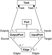
Figure 2-1: Native model of Workflow
In our model, Tasks represent units of work, and Edges represent the connections (flows of control and data) between them. Each Edge flows from an OutputPort on a Task to an InputPort on another Task, indicating that data resulting from the completion of the source's Task becomes the input of the target's Task. We have used the multiplicity of the references from Task to InputPort and OutputPort, to express the constraint that each Task must have at least one InputPort and at least one OutputPort.
We construct our model as described in Chapter 1, "Introduction to EMF" on page 3. We use the Sample Ecore Model Editor, but you may choose to edit the XMI directly, or use the Omondo EclipseUML plug-in. We create an EPackage named workflow, and within it, create EClasses to represent Task, Edge, Port, OutputPort, and InputPort.
| Tip | If you are using the model to drive code generation, we suggest that you follow Java conventions for naming model elements:
|
Example 2-1 shows the XML Metadata Interchange (XMI) that represents the workflow EPackage. Each EClass is represented as an eClassifiers element nested within the workflow EPackage element.
Example 2-1: XMI for model of Workflow
<ecore:EPackage xmi:version="2.0" xmlns:xmi="http://www.omg.org/XMI" xmlns:xsi="http://www.w3.org/2001/XMLSchema-instance" name="workflow" xmlns:ecore="http://www.eclipse.org/emf/2002/Ecore" nsPrefix="workflow" nsURI="http://www.redbooks.ibm.com/sal330r/example/workflow1"> <eClassifiers xsi:type="ecore:EClass" name="Task"> <eReferences name="inputs" eType="#//InputPort" lowerBound="1" upperBound="-1" containment="true" eOpposite="#//InputPort/task"/> <eReferences name="outputs" eType="#//OutputPort" lowerBound="1" upperBound="-1" containment="true" eOpposite="#//OutputPort/task"/> </eClassifiers> <eClassifiers xsi:type="ecore:EClass" name="Port" abstract="true"/> <eClassifiers xsi:type="ecore:EClass" name="Edge"> <eReferences name="target" eType="#//InputPort" lowerBound="1" eOpposite="#//InputPort/edges"/> <eReferences name="source" eType="#//OutputPort" lowerBound="1" eOpposite="#//OutputPort/edges"/> </eClassifiers> <eClassifiers xsi:type="ecore:EClass" name="InputPort" eSuperTypes="#//Port"> <eReferences name="edges" eType="#//Edge" upperBound="-1" eOpposite="#//Edge/target"/> <eReferences name="task" eType="#//Task" lowerBound="1" eOpposite="#//Task/inputs"/> </eClassifiers> <eClassifiers xsi:type="ecore:EClass" name="OutputPort" eSuperTypes="#//Port"> <eReferences name="edges" eType="#//Edge" upperBound="-1" eOpposite="#//Edge/source"/> <eReferences name="task" eType="#//Task" lowerBound="1" eOpposite="#//Task/outputs"/> </eClassifiers> </ecore:EPackage>
Although we have shown associations in the Class Diagram in Figure 2-1, the Ecore model does not represent associations explicitly. Instead, we use an EReference to represent each navigable end of an association. An association that is navigable in both directions is represented by two EReferences, one on each associated class, with eOpposites that refer to each other. For example, the association between Edge and InputPort is navigable from both ends, and so we see the edges EReference in InputPort and the target EReference in Edge. It is important to make sure that the eOpposites of a pair of corresponding EReferences match, and that both EReferences have their eOpposite set.
An association that is navigable in one direction only is represented as a single EReference, with no eOpposite. The multiplicity of the association ends is represented by the upperBound and lowerBound attributes on the eReferences elements representing each EReference.
As we can see from our example, associations that represent containment, such as the associations between Task and Ports, are represented by an EReference where containment is true, on the containing class. The containment of the InputPorts and OutputPorts within Tasks is represented by the inputs and outputs eReferences inside the Task eClassifiers element.
The inheritance of ports is represented by the eSuperTypes attribute on the InputPort and OutputPort elements. The EClass Port is an abstract class, which is indicated by the value of the abstract attribute on the eClassifiers element representing Port.
When we generate an EMF.Edit-based editor from our model, as described in the EMF documentation, and use it to create Tasks and Edges, we can immediately see a problem with this model. Using the generated editor, we can only create Tasks and Edges separately; we are missing a class that we could instantiate to contain all of the tasks and edges in our workflow. The solution is to add an additional class, Workflow, that contains both Tasks and Edges.
| Tip | It is often useful to design models around a containment-based hierarchy rooted at a single class. This approach can make it easier to work with instances, as you have a single entry point from which you can access all of the other objects in the instance (directly or indirectly), and it means that all of the objects will be serialized into a single XMI document by default. We discuss this in more detail in 2.3.2, "Default serialization of model instances" on page 66. If you wish to have the flexibility of choosing whether or not to contain instance objects in the top-level container, make sure that any references back to the container have a lowerBound of zero. |
Figure 2-2 shows the model with the additional Workflow class.
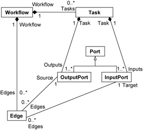
Figure 2-2: Model of Workflow with additional Workflow class
Example 2-2 shows the XMI fragment that represents the Workflow class. The eClassifiers element is added to the contents of the workflow EPackage. References to the Workflow are also added to Task and Edge as eReferences elements within the eClassifiers representing each class, for example: <eReferences name="workflow" eType="#//Workflow" lowerBound="1" eOpposite="#//Workflow/edges"/>
Example 2-2: XMI fragment for Workflow class
<eClassifiers xsi:type="ecore:EClass" name="Workflow"> <eReferences name="tasks" eType="#//Task" upperBound="-1" containment="true" eOpposite="#//Task/workflow"/> <eReferences name="edges" eType="#//Edge" upperBound="-1" containment="true" eOpposite="#//Edge/workflow"/> </eClassifiers>
When we start adding detail to the classes that we use to model workflow, we notice that many of the elements share common features, such as name. This is often the case when modelling, and it is usual to create a common supertype that represents an abstraction of all objects in the model, and which provides these common features. When you are using such a model, you have the benefit of knowing that all objects in the model are of that type, which can be useful when you are working with the objects reflectively. For EMF models, this is less of an issue, as all model elements already have a common supertype, EObject, and a rich reflective API is provided to allow you to work with your model objects in this way.
Figure 2-3 shows the model with the added WorkflowElement class.
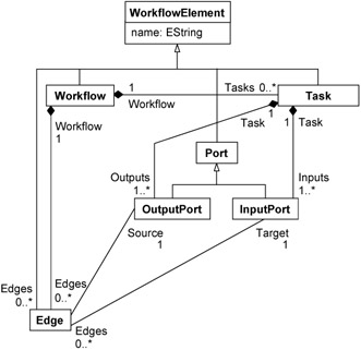
Figure 2-3: Model of Workflow with additional common supertype
Working with packages
EPackages are used to collect EClasses and EDataTypes together in much the same way that packages are used in Java. In this section, we discuss models that span multiple packages.
Typically packages are used to group related concepts into reusable modules. When creating an editor for a model, it is often necessary to store additional information about model objects, such as layout information or display properties. For the sample application described in Chapter 7, "Implementing the sample" on page 203, we add this information directly to the WorkflowModel; however, another approach is to use a separate package to represent the information about each diagram.
We create an EPackage Diagram, and within it, classes to represent connected and contained nodes within that diagram, as Figure 2-4 shows. Display properties such as the x and y co-ordinates, width and height, are represented by EAttributes belonging to DiagramNode.
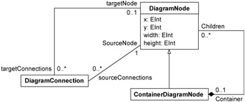
Figure 2-4: DiagramModel
The following examples illustrate two ways of using our DiagramModel and WorkflowModel together:
-
We construct a new package WorkflowDiagram, which merges concepts from the two packages using inheritance.
-
We store the diagram information separately from the workflows, using references between DiagramNode and DiagramConnection and the appropriate classes from the WorkflowModel to maintain the relationship between the two models.
For the first approach, we create a new package WorkflowDiagramPackage, which contains classes that combine concepts from the WorkflowModel and the DiagramModel. For example, a Task in a Diagram is represented by a WorkflowDiagramTask, which inherits from both Task and DiagramNode. Notice that we identify types defined in another package by the Ecore file that contains the type, followed by the usual reference to the type itself. Also notice that the multiple inheritance is represented by a space separated list within the eSuperTypes attribute. We choose to specify the corresponding classes from the WorkflowModel as the primary supertypes of the classes in the WorkflowDiagram model, and so they appear in the eSuperTypes list first.
Example 2-3: Importing the DiagramModel and WorkflowModel
<ecore:EPackage xmi:version="2.0" xmlns:xmi="http://www.omg.org/XMI" xmlns:xsi="http://www.w3.org/2001/XMLSchema-instance" nsPrefix="wfDiagram" xmlns:ecore="http://www.eclipse.org/emf/2002/Ecore" name="WorkflowDiagram" nsURI="http://www.redbooks.ibm.com/sal330r/example/workflowdiagram"> <eClassifiers xsi:type="ecore:EClass" name="WorkflowDiagramTask" eSuperTypes="workflowWithSupertype.ecore#//Task Diagram.ecore#//DiagramNode"/> <eClassifiers xsi:type="ecore:EClass" name="WorkflowDiagramWorkflow" eSuperTypes="workflowWithSupertype.ecore#//Workflow Diagram.ecore#//DiagramNode"/> <eClassifiers xsi:type="ecore:EClass" name="WorkflowDiagramEdge" eSuperTypes="workflowWithSupertype.ecore#//Edge Diagram.ecore#//DiagramNode"/> </ecore:EPackage>
In the second approach, the diagram and the workflow are more loosely coupled. We add references to the classes in the DiagramModel to represent the linkage between the two models, as shown in Example 2-4.
Example 2-4: DiagramModel with references to WorkflowModel objects
<ecore:EPackage xmi:version="2.0" xmlns:xmi="http://www.omg.org/XMI" xmlns:xsi="http://www.w3.org/2001/XMLSchema-instance" nsPrefix="diagram" xmlns:ecore="http://www.eclipse.org/emf/2002/Ecore" name="diagramwithrefs" nsURI="http://www.redbooks.ibm.com/sal330r/example/diagram"> <eClassifiers xsi:type="ecore:EClass" name="DiagramNode"> <eReferences name="container" eType="#//ContainerDiagramNode" eOpposite="#//ContainerDiagramNode/children"/> <eReferences name="model" eType="ecore:EClass WorkflowWithCommonSupertype.ecore#//Task"/> <eReferences name="sourceConnections" eType="#//DiagramConnection" upperBound="-1" eOpposite="#//DiagramConnection/sourceNode"/> <eReferences name="targetConnections" eType="#//DiagramConnection" upperBound="-1" eOpposite="#//DiagramConnection/targetNode"/> <eAttributes name="x" eType="ecore:EDataType http://www.eclipse.org/emf/2002/Ecore#//EInt"/> <eAttributes name="y" eType="ecore:EDataType http://www.eclipse.org/emf/2002/Ecore#//EInt"/> <eAttributes name="width" eType="ecore:EDataType http://www.eclipse.org/emf/2002/Ecore#//EInt"/> <eAttributes name="height" eType="ecore:EDataType http://www.eclipse.org/emf/2002/Ecore#//EInt"/> </eClassifiers> <eClassifiers xsi:type="ecore:EClass" name="DiagramConnection"> <eReferences name="sourceNode" eType="#//DiagramNode" lowerBound="1" eOpposite="#//DiagramNode/sourceConnections"/> <eReferences name="targetNode" eType="#//DiagramNode" eOpposite="#//DiagramNode/targetConnections"/> <eReferences name="model" eType="ecore:EClass WorkflowWithCommonSupertype.ecore#//Edge"/> </eClassifiers> <eClassifiers xsi:type="ecore:EClass" name="ContainerDiagramNode" eSuperTypes="#//DiagramNode"> <eReferences name="children" eType="#//DiagramNode" upperBound="-1" containment="true" eOpposite="#//DiagramNode/container"/> <eReferences name="model" eType="ecore:EClass WorkflowWithCommonSupertype.ecore#//Workflow"/> </eClassifiers> </ecore:EPackage>
Notice that because we are referencing classes from another package, we have to be explicit about the type. For example, we refer to the Task class as follows:
<eReferences name="model" eType="ecore:EClass WorkflowWithCommonSupertype.ecore#//Task"/>
Notice also that the references are one-way references, as we do not wish to pollute the WorkflowModel with references to the DiagramModel.
The Ecore model also allows us to define nested packages, which are represented in the XMI as eSubpackages elements. For example, we could package the DiagramModel and the WorkflowModel together as sub-packages of a new package NestedWorkflowDiagram. Example 2-5 shows the XMI for our NestedWorkflowDiagram package, with some details omitted for brevity. Notice that reference strings also now include the subpackage, such as:
<eReferences name="model" eType="#//workflowsupertype/Edge"/>
Example 2-5: Using nested packages
<ecore:EPackage xmi:version="2.0" xmlns:xmi="http://www.omg.org/XMI" xmlns:xsi="http://www.w3.org/2001/XMLSchema-instance" nsPrefix="nested" xmlns:ecore="http://www.eclipse.org/emf/2002/Ecore" name="nested" nsURI="http://www.redbooks.ibm.com/sal330r/example/nested" > <eSubpackages name="workflowsupertype" nsPrefix="workflow" nsURI="http://www.redbooks.ibm.com/sal330r/example/workflow3"> ... contents of workflow package ... </eSubpackages> <eSubpackages name="diagram" nsPrefix="diagram" nsURI="http://www.redbooks.ibm.com/sal330r/example/diagram"> ... DiagramNode class ... <eClassifiers xsi:type="ecore:EClass" name="DiagramConnection"> <eReferences name="model" eType="#//workflowsupertype/Edge"/> <eReferences name="sourceNode" eType="#//diagram/DiagramNode" lowerBound="1" eOpposite="#//diagram/DiagramNode/sourceConnections"/> <eReferences name="targetNode" eType="#//diagram/DiagramNode" eOpposite="#//diagram/DiagramNode/targetConnections"/> </eClassifiers> <eClassifiers xsi:type="ecore:EClass" name="ContainerDiagramNode" eSuperTypes="#//diagram/DiagramNode"> <eReferences name="model" eType="#//workflowsupertype/Workflow"/> <eReferences name="children" eType="#//diagram/DiagramNode" upperBound="-1" containment="true" eOpposite="#//diagram/DiagramNode/container"/> </eClassifiers> </eSubpackages> </ecore:EPackage>
| Tip | When using nested sub-packages, be sure that each package has a unique nsURI. |
Declaring datatypes
EMF provides datatypes such as EString and EInt, which represent the basic Java types that you can use for simple attributes. If you need to use a different Java type, you need to create an EDataType to represent it. For example, we use EString to represent attributes such as condition of ConditionalOutputPort and whileCondition for LoopTask from the WorkflowModel for the sample application. If we wanted to represent these conditions with a specific existing Java type instead, we would declare an EDataType corresponding to that type, as follows:
<eClassifiers xsi:type="ecore:EDataType" name="Condition" instanceClassName="com.example.Condition"/>
Adding operations
We can augment the classes in our model by adding operations to them. Aside from the convenience of having the signatures and skeletons generated into the code, there is little difference between adding the operations directly to the code as methods and adding the operations to the model. In both cases you will need to implement the methods in the generated code. A good approach is to define the signatures of the methods that you want to be public in your model, then complete the generated skeletons to implement them.
Annotating the model
The Ecore model includes an EAnnotation object that can be added to any model element. EAnnotations represent additional information that is associated with a model object, and they take the form of key and value pairs. You may choose to use EAnnotations to provide hints or additional information about how to use or represent model objects in an application, to represent additional constraints that are evaluated using another tool, or you may choose simply to use these annotations to document your model. An example of using EAnnotations to provide additional information about a model is described in 2.3.3, "Using the XSD plug-in to customize serialization" on page 70. The XSD plug-in uses EAnnotations to map model objects to XML.
2.1.2 Migrating existing models
The EMF documentation describes how to import from models expressed using annotated Java interfaces, models created using Rational Rose®, and models represented by an XML Schema. In this section, we discuss migrating existing models, focusing on migrating an XML Schema to EMF as an example. We provide examples to illustrate the correspondences between concepts from XML Schema and concepts provided by EMF Ecore.
For information about migrating models expressed using other frameworks, please refer to the following documents, which are linked from the documents section of the EMF project site at:
-
http://www.eclipse.org/emf/:
UML:
-
Tutorial: Generating an EMF model
-
Specifying Package Information in Rose
Annotated Java interfaces:
-
Tutorial: Generating an EMF model
-
Using EMF (Catherine Griffin's Eclipse Corner article)
Migrating from XML Schema to EMF is described in the Tutorial: Generating an EMF Model using XML Schema. The first page of the tutorial briefly outlines the mapping used to create EMF models from an XML Schema. In this section, we provide examples that illustrate this mapping. We use the purchase order XML Schema shown in Example 2-6 as the source for our new EMF model. Notice that this schema is taken from the XML Schema Part 0: Primer W3C Recommendation, 2 May 2001. [1] The examples for this section can be found in the MigrateFromXMLSchema project, in the examples provided with this book.
Example 2-6: Example XML Schema
<xsd:schema xmlns:xsd="http://www.w3.org/2001/XMLSchema"> <xsd:annotation> <xsd:documentation xml:lang="en"> Purchase order schema for Example.com. Copyright 2000 Example.com. All rights reserved. </xsd:documentation> </xsd:annotation> <xsd:element name="purchaseOrder" type="PurchaseOrderType"/> <xsd:element name="comment" type="xsd:string"/> <xsd:complexType name="PurchaseOrderType"> <xsd:sequence> <xsd:element name="shipTo" type="USAddress"/> <xsd:element name="billTo" type="USAddress"/> <xsd:element ref="comment" minOccurs="0"/> <xsd:element name="items" type="Items"/> </xsd:sequence> <xsd:attribute name="orderDate" type="xsd:date"/> </xsd:complexType> <xsd:complexType name="USAddress"> <xsd:sequence> <xsd:element name="name" type="xsd:string"/> <xsd:element name="street" type="xsd:string"/> <xsd:element name="city" type="xsd:string"/> <xsd:element name="state" type="xsd:string"/> <xsd:element name="zip" type="xsd:decimal"/> </xsd:sequence> <xsd:attribute name="country" type="xsd:NMTOKEN" fixed="US"/> </xsd:complexType> <xsd:complexType name="Items"> <xsd:sequence> <xsd:element name="item" minOccurs="0" maxOccurs="unbounded"> <xsd:complexType> <xsd:sequence> <xsd:element name="productName" type="xsd:string"/> <xsd:element name="quantity"> <xsd:simpleType> <xsd:restriction base="xsd:positiveInteger"> <xsd:maxExclusive value="100"/> </xsd:restriction> </xsd:simpleType> </xsd:element> <xsd:element name="USPrice" type="xsd:decimal"/> <xsd:element ref="comment" minOccurs="0"/> <xsd:element name="shipDate" type="xsd:date" minOccurs="0"/> </xsd:sequence> <xsd:attribute name="partNum" type="SKU" use="required"/> </xsd:complexType> </xsd:element> </xsd:sequence> </xsd:complexType> <!-- Stock Keeping Unit, a code for identifying products --> <xsd:simpleType name="SKU"> <xsd:restriction base="xsd:string"> <xsd:pattern value="\d{3}-[A-Z]{2}"/> </xsd:restriction> </xsd:simpleType> </xsd:schema> When we import our model, as the tutorial describes, each namespace declared as a targetNamespace of an XML Schema is represented in EMF as an EPackage. In our case, we only have one targetNamespace, so a single EPackage is created, as shown in Figure 2-5.
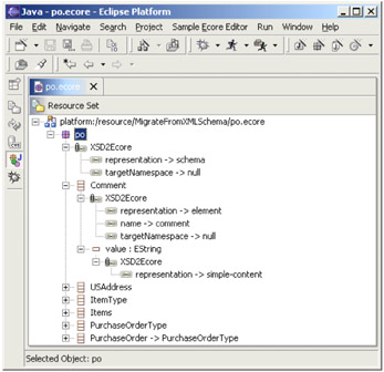
Figure 2-5: EMF model from XML Schema
If the schema that you are importing from has a targetNamespace, then the nsURI of the generated EPackage is set to that URI, and the name and nsPrefix are derived from that URI. For example, if the targetNamespace is http://www.example.com, then the nsPrefix is com.example, and the name is example. If the targetNamespace is http://www.example.com/foo, then the name is foo and the nsPrefix is com.example.foo.
Example 2-7 shows how the features of the EPackage created from po.xsd are populated by the mapping. The purchase order schema did not have a targetNamespace, so the URI to the schema file is used as the nsURI instead, and the name of the file is used for the nsPrefix and name.
Example 2-7: EPackage from XML Schema
<ecore:EPackage xmi:version="2.0" xmlns:xmi="http://www.omg.org/XMI" xmlns:xsi="http://www.w3.org/2001/XMLSchema-instance" xmlns:ecore="http://www.eclipse.org/emf/2002/Ecore" name="po" nsURI="platform:/resource/MigrateFromXMLSchema/po.xsd" nsPrefix="po"> ... </ecore:EPackage>
You may notice that the XSD plug-in generates EAnnotations for each of the objects in the model. These annotations describe how the model maps to the schema, and is used to serialize model instances so that they conform to the XML Schema from which the EMF model was generated. We discuss how to modify these annotations to control serialization in 2.3.3, "Using the XSD plug-in to customize serialization" on page 70.
Types from the XML Schema become EClassifiers: complex types, which represent types that contain elements or attributes, are represented by EClasses in EMF. Example 2-8 shows the EClass mapped from the USAddress complex type. Notice that the representation of this EClass is type, because it has been generated from a type.
Example 2-8: EClass for the USAddress type
<eClassifiers xsi:type="ecore:EClass" name="USAddress"> <eAnnotations source="http:///org/eclipse/emf/mapping/xsd2ecore/XSD2Ecore"> <details key="representation" value="type"/> <details key="name" value="USAddress"/> <details key="targetNamespace"/> </eAnnotations> ... </eClassifiers>
Elements of this type are mapped to EReferences within the EClass representing the containing type. For example, the USAddress type is the type of the shipTo element, contained within the PurchaseOrderType. Hence, as shown in Example 2-9, shipTo is represented as an EReference within the EClass created for PurchaseOrderType. Notice that the representation is element, because the EReference was mapped from an element declaration in the XML Schema.
Example 2-9: EReference for element of complex type
<eReferences name="shipTo" eType="#//USAddress" lowerBound="1" containment="true"> <eAnnotations source="http:///org/eclipse/emf/mapping/xsd2ecore/XSD2Ecore"> <details key="representation" value="element"/> <details key="name" value="shipTo"/> <details key="targetNamespace"/> </eAnnotations> </eReferences>
EDataTypes are used to represent simple types that represent atomic values. For example, SKU is represented by EString in the model. For XML elements that are of a simple type, such as Comment from the purchase order schema, an EClass representing the element is created, and an EAttribute is used to represent the content. Example 2-10 shows the Comment EClass. Notice that the representation of the value attribute is simple-content, that is, it provides the actual content of the comment element.
Example 2-10: EClass from simple-typed element
<eClassifiers xsi:type="ecore:EClass" name="Comment"> <eAnnotations source="http:///org/eclipse/emf/mapping/xsd2ecore/XSD2Ecore"> <details key="representation" value="element"/> <details key="name" value="comment"/> <details key="targetNamespace"/> </eAnnotations> <eAttributes name="value" eType="ecore:EDataType http://www.eclipse.org/emf/2002/Ecore#//EString"> <eAnnotations source="http:///org/eclipse/emf/mapping/xsd2ecore/XSD2Ecore"> <details key="representation" value="simple-content"/> </eAnnotations> </eAttributes> </eClassifiers>
Every simple-typed attribute in the XML Schema maps to an EAttribute belonging to the EClass mapped from the containing XML element. When the type of the XML Schema attribute has been mapped to an EClass (which is true for types such as anyURI), then the attribute is mapped to an EReference instead. We see an example in Example 2-11. The representation is attribute to indicate that it was mapped from an XML attribute.
Example 2-11: EAttribute from XML attributes
<eAttributes name="orderDate" eType="ecore:EDataType http://www.eclipse.org/emf/2002/Ecore#//EString"> <eAnnotations source="http:///org/eclipse/emf/mapping/xsd2ecore/XSD2Ecore"> <details key="representation" value="attribute"/> <details key="name" value="orderDate"/> <details key="targetNamespace"/> </eAnnotations> </eAttributes>
[1]Copyright ©2001 W3C® (MIT, INRIA, Keio), All Rights Reserved. W3C liability, trademark, document use and software licensing rules apply. http://www.w3.org/Consortium/Legal/
|
| < Day Day Up > |
|
EAN: 2147483647
Pages: 70