Working with the Bus Driver
Working with the Bus Driver
In contrast with drivers for devices that attach to traditional PC buses such as Peripheral Component Interconnect (PCI), a USB device driver never talks directly to its hardware. Instead, it creates an instance of the data structure known as the USB request block, which it then submits to the parent driver.
You submit USB request blocks (URBs) to the parent driver using an IRP with the major function code IRP_MJ_INTERNAL_DEVICE_CONTROL. In some situations, you can directly call a function using the parent driver s direct-call interface. The parent driver in turn schedules bus time in some frame or another to carry out the operation encoded in the URB.
In this section, I ll describe the mechanics of working with the parent driver to carry out the typical operations a USB function driver performs. I ll first describe how to build and submit a URB. Then I ll discuss the mechanics of configuring and reconfiguring your device. Finally I ll outline how your driver can manage each of the four types of communication pipes.
Initiating Requests
To create a URB, you allocate memory for the URB structure and invoke an initialization routine to fill in the appropriate fields for the type of request you re about to send. Suppose, for example, that you were beginning to configure your device in response to an IRP_MN_START_DEVICE request. One of your first tasks might be to read the device descriptor. You might use the following snippet of code to accomplish this task:
USB_DEVICE_DESCRIPTOR dd; URB urb; UsbBuildGetDescriptorRequest(&urb, sizeof(_URB_CONTROL_DESCRIPTOR_REQUEST), USB_DEVICE_DESCRIPTOR_TYPE, 0, 0, &dd, NULL, sizeof(dd), NULL);
We first declare a local variable (named urb) to hold a URB data structure. The URB is declared (in USBDI.H) as a union of several substructures, one for each of the requests you might want to make of a USB device. We re going to be using the UrbControlDescriptorRequest substructure of the URB union, which is declared as an instance of struct _URB_CONTROL_DESCRIPTOR_REQUEST. Using an automatic variable like this is fine if you know the stack has enough room to hold the largest possible URB and if you ll await completion of the URB before allowing the variable to pass out of scope.
You can, of course, dynamically allocate the memory for a URB from the heap if you want:
PURB urb = (PURB) ExAllocatePool(NonPagedPool, sizeof(_URB_CONTROL_DESCRIPTOR_REQUEST)); if (!urb) return STATUS_INSUFFICIENT_RESOURCES; UsbBuildGetDescriptorRequest(urb, ...);ExFreePool(urb);
UsbBuildGetDescriptorRequest is documented like a normal service routine, but it s actually a macro (declared in USBDLIB.H) that generates inline statements to initialize the fields of the get descriptor request substructure. The DDK headers define one of these macros for most types of URBs you might want to build. See Table 12-8. As is true of preprocessor macros in general, you should avoid using expressions that have side effects in the arguments to this macro.
| Helper Macro | Type of Transaction |
| UsbBuildInterruptOrBulkTransferRequest | Input or output to an interrupt or bulk endpoint |
| UsbBuildGetDescriptorRequest | GET_DESCRIPTOR control request for endpoint 0 |
| UsbBuildGetStatusRequest | GET_STATUS request for a device, an interface, or an endpoint |
| UsbBuildFeatureRequest | SET_FEATURE or CLEAR_FEATURE request for a device, an interface, or an endpoint |
| UsbBuildSelectConfigurationRequest | SET_CONFIGURATION |
| UsbBuildSelectInterfaceRequest | SET_INTERFACE |
| UsbBuildVendorRequest | Any vendor-defined control request |
In the preceding code fragment, we specify that we want to retrieve the device descriptor information in a local variable (dd) whose address and length we supply. URBs that involve data transfer allow you to specify a nonpaged data buffer in either of two ways. You can specify the virtual address and length of the buffer, as I did in the fragment. Alternatively, you can supply a memory descriptor list (MDL) for which you ve already done the probe-and-lock step by calling MmProbeAndLockPages.
More About URBs
Internally, the bus driver always uses an MDL to describe data buffers. If you specify a buffer address, the parent driver creates the MDL itself. If you happen to already have an MDL, it would be counterproductive to call MmGetSystemAddressForMdlSafe and pass the resulting virtual address to the parent driver: the parent driver will turn around and create another MDL to describe the same buffer!The URB also has a chaining field named Urblink that the parent driver uses internally to submit a series of URBs all at once to the host controller driver. The various macro functions for initializing URBs also have an argument in which you can theoretically supply a value for this linking field. You and I should always supply NULL because the concept of linked URBs hasn t been fully implemented trying to link data transfer URBs will lead to system crashes, in fact.
Sending a URB
Having created a URB, you need to create and send an internal IOCTL request to the parent driver, which is sitting somewhere lower in the driver hierarchy for your device. In many cases, you ll want to wait for the device s answer, and you ll use a helper routine like this one:
NTSTATUS SendAwaitUrb(PDEVICE_OBJECT fdo, PURB urb) { PDEVICE_EXTENSION pdx = (PDEVICE_EXTENSION) fdo->DeviceExtension; KEVENT event; KeInitializeEvent(&event, NotificationEvent, FALSE); IO_STATUS_BLOCK iostatus; PIRP Irp = IoBuildDeviceIoControlRequest (IOCTL_INTERNAL_USB_SUBMIT_URB, pdx->LowerDeviceObject, NULL, 0, NULL, 0, TRUE, &event, &iostatus); PIO_STACK_LOCATION stack = IoGetNextIrpStackLocation(Irp); stack->Parameters.Others.Argument1 = (PVOID) urb; NTSTATUS status = IoCallDriver(pdx->LowerDeviceObject, Irp); if (status == STATUS_PENDING) { KeWaitForSingleObject(&event, Executive, KernelMode, FALSE, NULL); status = iostatus.Status; } return status; } This is simply an example of creating and sending a synchronous IRP to another driver (scenario 6 from Chapter 5). The only wrinkle is the precise way the URB letter is stuffed into the INTERNAL_DEVICE_CONTROL envelope : by setting the stack Parameters.Others.Argument1 field to point to the URB.
NOTE
It bears emphasizing that drivers package URBs into normal IRPs with the major function code IRP_MJ_INTERNAL_DEVICE_CONTROL. To provide for an upper filter driver to send its own URBs, every driver for a USB device should have a dispatch function that passes this IRP down to the next layer.
Status Returns from URBs
When you submit a URB to the USB bus driver, you eventually receive back an NTSTATUS code that describes the result of the operation. Internally, the bus driver uses another set of status codes with the typedef name USBD_STATUS. These codes are not NTSTATUS codes.
When the parent driver completes a URB, it sets the URB s UrbHeader.Status field to one of these USBD_STATUS values. You can examine this value in your driver to glean more information about how your URB fared. The URB_STATUS macro in the DDK simplifies accessing:
NTSTATUS status = SendAwaitUrb(fdo, &urb); USBD_STATUS ustatus = URB_STATUS(&urb);
There s no particular protocol for preserving this status and passing it back to an application, however. You re pretty much free to do what you will with it.
Configuration
The USB bus driver automatically detects attachment of a new USB device. It then reads the device descriptor structure to determine what sort of device has suddenly appeared. The vendor and product identifier fields of the descriptor, together with other descriptors, determine which driver needs to be loaded.
The Configuration Manager calls the driver s AddDevice function in the normal way. AddDevice does all the tasks you ve already heard about: it creates a device object, links the device object into the driver hierarchy, and so on. The Configuration Manager eventually sends the driver an IRP_MN_START_DEVICE Plug and Play request. Back in Chapter 6, I showed you how to handle that request by calling a helper function named StartDevice with arguments describing the translated and untranslated resource assignments for the device. One piece of good news is that you needn t worry about I/O resources at all in a USB driver because you have none. So you can write a StartDevice helper function with the following skeletal form:
NTSTATUS StartDevice(PDEVICE_OBJECT fdo) { PDEVICE_EXTENSION pdx = (PDEVICE_EXTENSION) fdo->DeviceExtension; <configure device> return STATUS_SUCCESS; } I glibly said configure device where you ll write rather a lot of code to configure the hardware. But as I said, you needn t concern yourself with I/O ports, interrupts, direct memory access (DMA) adapter objects, or any of the other resource-oriented elements I described in Chapter 7.
Where s the Driver?
I ll discuss the mechanics of installing WDM drivers in Chapter 15. It will help to understand some of those details right now, however. Let s suppose that your device has the vendor ID 0x0547 and the product ID 0x102A. I ve borrowed the vendor ID belonging to Cypress Semiconductor (with their permission) for purposes of this illustration. I m using the product ID for the USB42 sample (the Answer Device) that you ll find in the companion content.USB describes many methods for the operating system to locate a device driver (or set of drivers) based on the device, configuration, and interface descriptors on a device. See Universal Serial Bus Common Class Specification (Rev. 1.0, December 16, 1997), Section 3.10. My samples all rely on the second-highest priority method, whereby the vendor and product identifiers alone determine the driver.
Confronted with a device having the vendor and product identifiers I just mentioned, the PnP Manager will look for a registry entry that contains information about a device named USB\VID_0547&PID_102A. If no such entry exists in the registry, the PnP Manager will trigger the new hardware wizard to locate an INF file describing such a device. The wizard might prompt the end user for a disk, or it might find the INF file already present on the computer. The wizard will then install the driver and populate the registry. Once the PnP Manager locates the registry entries, it can dynamically load the driver. That s where we come in.
The executive overview of what you need to accomplish in StartDevice is as follows. First you ll select a configuration for the device. If your device is like most devices, it has just one configuration. Once you select the configuration, you choose one or more of the interfaces that are part of that configuration. It s not uncommon for a device to support multiple interfaces, by the way. Having chosen a configuration and a set of interfaces, you send a select configuration URB to the bus driver. The bus driver in turn issues commands to the device to enable the configuration and interfaces. The bus driver creates pipes that allow you to communicate with the endpoints in the selected interfaces and provides handles by which you can access the pipes. It also creates handles for the configuration and the interfaces. You extract the handles from the completed URB and save them for future use. That accomplished, you re done with the configuration process.
Composite Devices
If your device has one configuration and multiple interfaces, the Microsoft generic parent driver will handle it automatically as a composite, or multifunction, device. You supply function drivers for each of the interfaces on the device by using INF files that specify the subfunction index along with a vendor and product ID. The generic parent driver creates a physical device object (PDO) for each interface, whereupon the PnP Manager loads the separate function drivers you ve provided. When one of these function drivers reads a configuration descriptor, the generic parent driver provides an edited version of the descriptor that describes just one interface.Refer to Chapter 15 for more information about the possible forms of device identifier in an INF file.
Reading a Configuration Descriptor
It s best to think of a fixed-size configuration descriptor as the header for a variable-length structure that describes a configuration, all its interfaces, and all the interfaces endpoints. See Figure 12-14.
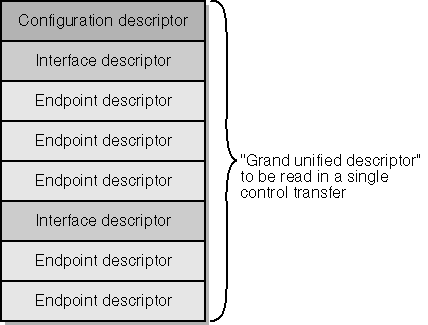
Figure 12-14. Structure of a configuration descriptor.
You must read the entire variable-length structure into a contiguous area of memory because the hardware won t allow you to directly access the interface and endpoint descriptors. Unfortunately, you don t initially know how long the combined structure is. The following fragment of code shows how you can use two URBs to read a configuration descriptor:
ULONG iconfig = 0; URB urb; USB_CONFIGURATION_DESCRIPTOR tcd; UsbBuildGetDescriptorRequest(&urb, sizeof(_URB_CONTROL_DESCRIPTOR_REQUEST), USB_CONFIGURATION_DESCRIPTOR_TYPE, iconfig, 0, &tcd, NULL, sizeof(tcd), NULL); SendAwaitUrb(fdo, &urb); ULONG size = tcd.wTotalLength; PUSB_CONFIGURATION_DESCRIPTOR pcd = (PUSB_CONFIGURATION_DESCRIPTOR) ExAllocatePool( NonPagedPool, size); UsbBuildGetDescriptorRequest(&urb, sizeof(_URB_CONTROL_DESCRIPTOR_REQUEST), USB_CONFIGURATION_DESCRIPTOR_TYPE, iconfig, 0, pcd, NULL, size, NULL); SendAwaitUrb(fdo, &urb);
In this fragment, we issue one URB to read a configuration descriptor I specified an index of 0 to get the first one into a temporary descriptor area named tcd. This descriptor contains the length (wTotalLength) of the combined structure, which includes configuration, interface, and endpoint descriptors. We allocate that much memory and issue a second URB to read the entire descriptor. At the end of the process, the pcd variable points to the whole shebang. (Don t leave out the error checking as I just did see the code samples in the companion content for examples of how to handle the many errors that might arise in this short sequence.)
TIP
You read configuration descriptors using a zero-based index. When the bus driver eventually issues a control transaction to enable that configuration, it uses the bConfigurationValue from the configuration descriptor. Usually, there s just one configuration descriptor numbered 1 that you read using index 0. Are there any readers who aren t dizzy yet?
If your device has a single configuration, go ahead to the next step using the descriptor set you ve just read. Otherwise, you ll need to enumerate the configurations (that is, step the iconfig variable from 0 to 1 less than the bNumConfigurations value in the device descriptor) and apply some sort of algorithm to pick from among them.
Selecting the Configuration
You eventually have to select a configuration by sending a series of control commands to the device to set the configuration and enable the desired interfaces. We ll be using a function named USBD_CreateConfigurationRequestEx to create the URB for this series of commands. One of its arguments is an array of pointers to descriptors for the interfaces you intend to enable. Your next step in configuration after settling on the configuration you want to use, therefore, is to prepare this array.
Reading a String Descriptor
For reporting or other purposes, you might want to retrieve some of the string descriptors that your device might provide. In the USB42 sample, for example, the device contains English-language descriptors for the vendor, product, and serial number as well as for the single configuration and interface supported by the device. I wrote the following helper function for reading string descriptors:NTSTATUS GetStringDescriptor(PDEVICE_OBJECT fdo, UCHAR istring, PUNICODE_STRING s) { NTSTATUS status; PDEVICE_EXTENSION pdx = (PDEVICE_EXTENSION) fdo->DeviceExtension; URB urb; UCHAR data[256]; if (!pdx->langid) { UsbBuildGetDescriptorRequest(&urb, sizeof(_URB_CONTROL_DESCRIPTOR_REQUEST), USB_STRING_DESCRIPTOR_TYPE, 0, 0, data, NULL, sizeof(data), NULL); status = SendAwaitUrb(fdo, &urb);if (!NT_SUCCESS(status)) return status; pdx->langid = *(LANGID*)(data + 2); } UsbBuildGetDescriptorRequest(&urb, sizeof(_URB_CONTROL_DESCRIPTOR_REQUEST), USB_STRING_DESCRIPTOR_TYPE, istring, pdx->langid, data, NULL, sizeof(data), NULL); status = SendAwaitUrb(fdo, &urb); if (!NT_SUCCESS(status)) return status; ULONG nchars = (data[0] - sizeof(WCHAR)) / sizeof(WCHAR); if (nchars > 257) nchars = 257; PWSTR p = (PWSTR) ExAllocatePool(PagedPool, (nchars + 1) * sizeof(WCHAR)); if (!p) return STATUS_INSUFFICIENT_RESOURCES; RtlCopyMemory(p, data + 2, nchars * sizeof(WCHAR)); p[nchars] = 0; s->Length = (USHORT) (sizeof(WCHAR) * nchars); s->MaximumLength = (USHORT) ((sizeof(WCHAR) * nchars) + sizeof(WCHAR)); s->Buffer = p; return STATUS_SUCCESS; }
The new and interesting part of this function given that you already know a lot about kernel-mode programming if you ve been reading this book sequentially is the initialization of the URB to fetch a string descriptor. In addition to supplying the index of the string we want to get, we also supply a standard LANGID language identifier. This is the same kind of language identifier that you use in a Win32 application. As I mentioned earlier, devices can provide strings in multiple languages, and string descriptor 0 contains a list of the supported language identifiers. To be sure to always ask for a supported language, I read string 0 the first time this routine executes and arbitrarily choose the first language as the one to ask for. In the actual sample drivers, the identifier will always be 0x0409, which identifies American English. The parent driver passes this language identifier along with the string index as a parameter for the get descriptor request it sends to the device. The device itself is responsible for deciding which string to return.
The output from my GetStringDescriptor function is a UNICODE_STRING that you use in the normal way. You would eventually call RtlFreeUnicodeString to release the string buffer.
I used GetStringDescriptor in the USB42 sample to generate extra debugging output about the device. For example, StartDevice contains code similar to this fragment:
UNICODE_STRING sd; if (pcd->iConfiguration && NT_SUCCESS(GetStringDescriptor(fdo, pcd->iConfiguration, &sd))) { KdPrint(("USB42 - Selecting configuration named %ws\n", sd.Buffer)); RtlFreeUnicodeString(&sd); }I actually used a macro so that I wouldn t have to type this same code a bunch of times, but you get the idea.
Recall that when we read the configuration descriptor, we also read all of its interface descriptors into adjacent memory. This memory therefore contains a series of descriptors: a configuration descriptor, an interface descriptor followed by all of its endpoints, another interface descriptor followed by all of its endpoints, and so on. One way of choosing interfaces is to parse through this collection of descriptors and remember the addresses of the interface descriptors you re interested in. The bus driver provides a routine named USBD_ParseConfigurationDescriptorEx to simplify that task:
PUSB_INTERFACE_DESCRIPTOR pid; pid = USBD_ParseConfigurationDescriptorEx(pcd, StartPosition, InterfaceNumber, AlternateSetting, InterfaceClass, InterfaceSubclass, InterfaceProtocol);
In this function, pcd is the address of the grand unified configuration descriptor. StartPosition is either the address of the configuration descriptor (the first time you make this call) or the address of a descriptor at which you want to begin searching. The remaining parameters specify criteria for a descriptor search. The value -1 indicates that you don t want the corresponding criterion to be employed in the search. You can look for the next interface descriptor that has zero or more of these attributes:
-
The given InterfaceNumber
-
The given AlternateSetting index
-
The given InterfaceClass index
-
The given InterfaceSubclass index
-
The given InterfaceProtocol index
When USBD_ParseConfigurationDescriptorEx returns an interface descriptor to you, you save it as the InterfaceDescriptor member of an element in an array of USBD_INTERFACE_LIST_ENTRY structures, and then you advance past the interface descriptor so that you can parse the next one. The array of interface list entries will be one of the parameters to the eventual call to USBD_CreateConfigurationRequestEx, so I need to say a little more about it. Each entry in the array is an instance of the following structure:
typedef struct _USBD_INTERFACE_LIST_ENTRY { PUSB_INTERFACE_DESCRIPTOR InterfaceDescriptor; PUSBD_INTERFACE_INFORMATION Interface; } USBD_INTERFACE_LIST_ENTRY, *PUSBD_INTERFACE_LIST_ENTRY; When you initialize an entry in the array, you set the InterfaceDescriptor member equal to the address of an interface descriptor that you want to enable and you set the Interface member to NULL. You define one entry for each interface, and then you add another entry whose InterfaceDescriptor is NULL to mark the end. For example, in my USB42 sample, I know in advance that only one interface exists, so I use the following code to create the interface list:
PUSB_INTERFACE_DESCRIPTOR pid = USBD_ParseConfigurationDescriptorEx(pcd, pcd, -1, -1, -1, -1, -1); USBD_INTERFACE_LIST_ENTRY interfaces[2] = { {pid, NULL}, {NULL, NULL}, }; That is, I parse the configuration descriptor to locate the first (and only) interface descriptor. Then I define a two-element array to describe that one interface.
If you need to enable more than one interface because you re providing your own composite device support, you ll repeat the parsing call in a loop. For example:
ULONG size = (pcd->bNumInterfaces + 1) * sizeof(USBD_INTERFACE_LIST_ENTRY); PUSBD_INTERFACE_LIST_ENTRY interfaces = (PUSBD_INTERFACE_LIST_ENTRY) ExAllocatePool(NonPagedPool, size); RtlZeroMemory(interfaces, size); ULONG i = 0; PUSB_INTERFACE_DESCRIPTOR pid = (PUSB_INTERFACE_DESCRIPTOR) pcd;
while ((pid = USBD_ParseConfigurationDescriptorEx(pcd, pid, ...)))
interfaces[i++].InterfaceDescriptor = pid++;
-
We first allocate memory to hold as many interface list entries as there are interfaces in this configuration, plus one. We zero the entire array. Wherever we leave off in filling the array during the subsequent loop, the next entry will be NULL to mark the end of the array.
-
The parsing call includes whatever criteria are relevant to your device. In the first iteration of the loop, pid points to the configuration descriptor. In later iterations, it points just past the interface descriptor returned by the preceding call.
-
Here we initialize the pointer to an interface descriptor. The postincrement of i causes the next iteration to initialize the next element in the array. The postincrement of pid advances past the current interface descriptor so that the next iteration parses the next interface. (If you call USBD_ParseConfigurationDescriptorEx with the second argument pointing to an interface descriptor that meets your criteria, you ll get back a pointer to that same descriptor. If you don t advance past that descriptor before making the next call, you re doomed to repeat the loop forever.)
The next step in the configuration process is to create a URB that we ll submit soon, I promise to configure the device:
PURB selurb = USBD_CreateConfigurationRequestEx(pcd, interfaces);
In addition to creating a URB (to which selurb points at this moment), USBD_CreateConfigurationRequestEx also initializes the Interface members of your USBD_INTERFACE_LIST entries to point to USBD_INTERFACE_INFORMATION structures. These information structures are physically located in the same memory block as the URB and will, therefore, be released back to the heap when you eventually call ExFreePool to return the URB. An interface information structure has the following declaration:
typedef struct _USBD_INTERFACE_INFORMATION { USHORT Length; UCHAR InterfaceNumber; UCHAR AlternateSetting; UCHAR Class; UCHAR SubClass; UCHAR Protocol; UCHAR Reserved; USBD_INTERFACE_HANDLE InterfaceHandle; ULONG NumberOfPipes; USBD_PIPE_INFORMATION Pipes[1]; } USBD_INTERFACE_INFORMATION, *PUSBD_INTERFACE_INFORMATION; The array of pipe information structures is what we re really interested in at this point since the other fields of the structure will be filled in by the parent driver when we submit this URB. Each of them looks like this:
typedef struct _USBD_PIPE_INFORMATION { USHORT MaximumPacketSize; UCHAR EndpointAddress; UCHAR Interval; USBD_PIPE_TYPE PipeType; USBD_PIPE_HANDLE PipeHandle; ULONG MaximumTransferSize; ULONG PipeFlags; } USBD_PIPE_INFORMATION, *PUSBD_PIPE_INFORMATION; So we have an array of USBD_INTERFACE_LIST entries, each of which points to a USBD_INTERFACE_INFORMATION structure that contains an array of USBD_PIPE_INFORMATION structures. Our immediate task is to fill in the Maximum TransferSize member of each of those pipe information structures if we don t want to accept the default value chosen by the parent driver. The default value is USBD_DEFAULT_MAXIMUM_TRANSFER_SIZE, which was equal to PAGE_SIZE in the DDK I was using at the time I wrote this book. The value we specify isn t directly related either to the maximum packet size for the endpoint (which governs how many bytes can be moved in a single bus transaction) or to the amount of data the endpoint can absorb in a series of transactions (which is determined by the amount of memory available on the device). Instead, it represents the largest amount of data we ll attempt to move with a single URB. This can be less than the largest amount of data that an application might send to the device or receive from the device, in which case our driver must be prepared to break application requests into pieces no bigger than this maximum size. I ll discuss how that task can be accomplished later in Managing Bulk Transfer Pipes.
The reason that we have to supply a maximum transfer size is rooted in the scheduling algorithm that the host controller drivers use to divide URB requests into transactions within bus frames. If we send a large amount of data, it s possible for our data to hog a frame to the exclusion of other devices. We therefore want to moderate our demands on the bus by specifying a reasonable maximum size for the URBs that we ll send at once.
The code needed to initialize the pipe information structures is something like this:
for (ULONG ii = 0; ii < <number of interfaces>; ++ii) { PUSBD_INTERFACE_INFORMATION pii = interfaces[ii].Interface; for (ULONG ip = 0; ip < pii->NumberOfPipes; ++ip) pii->Pipes[ip].MaximumTransferSize = <some constant>; }
NOTE
The USBD_CreateConfigurationRequestEx function initializes the MaximumTransferSize member of each pipe information structure to USBD_DEFAULT_MAXIMUM_TRANSFER_SIZE and the PipeFlags member to 0. Bear this in mind when you look at older driver samples and when you write your own driver.
Once you ve initialized the pipe information structures, you re finally ready to submit the configuration URB:
SendAwaitUrb(fdo, selurb);
Finding the Handles
Successful completion of the select configuration URB leaves behind various handle values that you should record for later use:
-
The UrbSelectConfiguration.ConfigurationHandle member of the URB is a handle for the configuration.
-
The InterfaceHandle member of each USBD_INTERFACE_INFOR MATION structure contains a handle for the interface.
-
Each of the USBD_PIPE_INFORMATION structures has a PipeHandle for the pipe ending in the corresponding endpoint.
For example, the USB42 sample records two handle values (in the device extension):
typedef struct _DEVICE_EXTENSION { USBD_CONFIGURATION_HANDLE hconfig; USBD_PIPE_HANDLE hpipe; } DEVICE_EXTENSION, *PDEVICE_EXTENSION; pdx->hconfig = selurb->UrbSelectConfiguration.ConfigurationHandle; pdx->hpipe = interfaces[0].Interface->Pipes[0].PipeHandle; ExFreePool(selurb); At this point in the program, the select configuration URB is no longer needed and can be discarded.
Shutting Down the Device
When your driver receives an IRP_MN_STOP_DEVICE request, you should place the device in its unconfigured state by creating and submitting a select configuration request with a NULL configuration pointer:
URB urb; UsbBuildSelectConfigurationRequest(&urb, sizeof(_URB_SELECT_CONFIGURATION), NULL); SendAwaitUrb(fdo, &urb);
Managing Bulk Transfer Pipes
The companion content has two sample programs that illustrate bulk transfers. The first and simplest is named USB42. It has an input bulk endpoint that delivers back the constant value 42 each time you read it. (I call this the Answer device because the number 42 is Douglas Adams s answer to the Ultimate Question of Life, the Universe and Everything in The Hitchhiker s Guide to the Galaxy.) The code to do the reading is as follows:
URB urb; UsbBuildInterruptOrBulkTransferRequest(&urb, sizeof(_URB_BULK_OR_INTERRUPT_TRANSFER), pdx->hpipe, Irp->AssociatedIrp.SystemBuffer, NULL, cbout, USBD_TRANSFER_DIRECTION_IN USBD_SHORT_TRANSFER_OK, NULL); status = SendAwaitUrb(fdo, &urb);
This code runs in the context of the handler for a DeviceIoControl call that uses the buffered method for data access, so the SystemBuffer field of the IRP points to the place to which data should be delivered. The cbout variable is the size of the data buffer we re trying to fill.
There s not much to explain about this request. You indicate with a flag whether you re reading (USBD_TRANSFER_DIRECTION_IN) or writing (USBD_TRANSFER_DIRECTION_OUT) the endpoint. You can optionally indicate with another flag bit (USBD_SHORT_TRANSFER_OK) whether you re willing to tolerate having the device provide less data than the maximum for the endpoint. The pipe handle is something you capture at IRP_MN_START_DEVICE time in the manner already illustrated.
Design of the LOOPBACK Sample
The LOOPBACK sample is considerably more complicated than USB42. The device it manages has two bulk transfer endpoints, one for input and another for output. You can feed up to 4096 bytes into the output pipe, and you can retrieve what you put in from the input pipe. The driver itself uses standard IRP_MJ_READ and IRP_MJ_WRITE requests for data movement.
LOOPBACK allows the application to read or write more than the pipe MaximumTransferSize during a single operation. This fact imposes constraints on how the driver works:
-
Each read or write IRP might require several stages to accomplish. In keeping with the USB specification (specifically, section 5.8.3), each stage except the last must be a multiple of the endpoint s maximum packet size.
-
It would obviously not do for the stages of different read or write requests to be intermixed at the device level. Therefore, LOOPBACK queues read and write requests to serialize access to the endpoint.
-
To avoid hassles related to IRP cancellation, LOOPBACK piggybacks its read and write URBs on the same IRP_MJ_READ or IRP_MJ_WRITE it receives from above.
LOOPBACK s StartIo Routine
The interesting routines in LOOPBACK are the StartIo routine that handles a single read or write request and the I/O completion routine for URB requests sent down to the bus driver. Both read and write IRPs feed into the same StartIo routine. The major reason why a single StartIo routine is appropriate in this driver is that we want to be doing either a read or a write, but not both simultaneously. Using a single routine is practical because there s very little difference in the way we handle reads and writes:
VOID StartIo(PDEVICE_OBJECT fdo, PIRP Irp) { PDEVICE_EXTENSION pdx = (PDEVICE_EXTENSION) fdo->DeviceExtension; PIO_STACK_LOCATION stack = IoGetCurrentIrpStackLocation(Irp); BOOLEAN read = stack->MajorFunctionCode == IRP_MJ_READ; USBD_PIPE_HANDLE hpipe = read ? pdx->hinpipe : pdx->houtpipe; ULONG urbflags = USBD_SHORT_TRANSFER_OK (read ? USBD_TRANSFER_DIRECTION_IN : USBD_TRANSFER_DIRECTION_OUT); } LOOPBACK sets the DO_DIRECT_IO flag in its device object. Consequently, the data buffer is described by an MDL whose address is at Irp->MdlAddress. We can determine the length of the requested transfer in two ways. We can fetch stack->Parameters.Read.Length or stack->Parameters.Write.Length. (Both Read and Write are identical substructures of the IO_STACK_LOCATION, by the way.) Alternatively, we can rely on the MDL:
ULONG length = Irp->MdlAddress ? MmGetMdlByteCount(Irp->MdlAddress) : 0;
Personally, I hate it when there are two ways of doing the same thing because then I worry that one of them will stop working in some future release of the operating system. I ve developed the habit of picking the most popular of alternatives in the belief that it s least likely to break over time. Most drivers I ve seen that use MDLs get the buffer length from the MDL. Therefore, I do too.
The next logical step in StartIo is to calculate the length of the first segment of a potentially multisegment transfer:
ULONG seglen = length; if (seglen > pdx->maxtransfer) seglen = pdx->maxtransfer;
(LOOPBACK s StartDevice function sets maxtransfer to the Maximum TransferSize for the input and output pipes. I made that equal to 1024 in this driver in order to exercise the multisegment transfer logic. The device firmware itself has a limit of 4096 bytes for a single logical transfer.)
Our call to UsbBuildInterruptOrBulkTransferRequest will be a bit more complicated than in the USB42 example because we re using DO_DIRECT_IO and because the transfer may require several stages. In preparation for that call, LOOPBACK creates a partial MDL, which describes just a portion of the entire buffer:
ULONG_PTR va = (ULONG_PTR) MmGetMdlVirtualAddress(Irp->MdlAddress); PMDL mdl = IoAllocateMdl((PVOID) (PAGE_SIZE - 1), seglen, FALSE, FALSE, NULL); IoBuildPartialMdl(Irp->MdlAddress, mdl, (PVOID) va, seglen);
This is the point in coding StartIo where you face a major decision. How will you create and send the one or more URBs that are required to perform this operation? One alternative, which I don t think is the best, is to create a series of IRP_MJ_INTERNAL_DEVICE_CONTROL requests, each with its own URB, and send them down the PnP stack to the USB bus driver. The reason I don t like this choice is that it requires a bunch of extra bookkeeping to control when you complete the main IRP and how you deal with cancellation of the main IRP. I actually followed this plan in the USBISO sample discussed later in this chapter, but there wasn t any sensible alternative in that case because of timing requirements.
The easier choice for a bulk transfer operation is to simply use and reuse the main IRP the one passed into StartIo, in other words as an envelope within which to stuff the URBs for successive stages. All we need to do is to initialize the next stack location by hand instead of by calling IoCopyCurrentIrpStackLocationToNext. Our StartIo routine then installs a completion routine and sends the main IRP down to the bus driver. Our completion routine recycles the IRP and the URB to perform the next stage of the transfer. When the last stage completes, our completion routine releases the memory occupied by the IRP and arranges to set IoStatus.Information equal to the number of bytes actually transferred, as required by the specifications for IRP_MJ_READ and IRP_MJ_WRITE.
Our completion routine actually needs a bit more information than just the URB address, however. I define the following context structure in LOOPBACK:
struct _RWCONTEXT : public _URB { ULONG_PTR va; // virtual address for next // segment of transfer ULONG length; // length remaining to transfer PMDL mdl; // partial MDL ULONG numxfer; // cumulative transfer count }; typedef struct _RWCONTEXT RWCONTEXT, *PRWCONTEXT; (This declaration relies on the fact that my drivers use C++ syntax, so I can derive one structure from another.) The initialization of the context structure is along these lines:
PRWCONTEXT ctx = (PRWCONTEXT) ExAllocatePool(NonPagedPool, sizeof(RWCONTEXT)); UsbBuildInterruptOrBulkTransferRequest(ctx, sizeof(_URB_BULK_OR_INTERRUPT_TRANSFER), hpipe, NULL, mdl, seglen, urbflags, NULL); ctx->va = va + seglen; ctx->length = length - seglen; ctx->mdl = mdl; ctx->numxfer = 0;
Notice that no cast operator is needed for ctx because it s derived from the URB structure. The MDL pointer for the URB is the partial MDL we created earlier, and the length is the chosen segment length.
After all of this initialization, we can finally prepare and send the IRP down to the bus driver:
stack = IoGetNextIrpStackLocation(Irp); stack->MajorFunction = IRP_MJ_INTERNAL_DEVICE_CONTROL; stack->Parameters.Others.Argument1 = (PVOID) (PURB) ctx; stack->Parameters.DeviceIoControl.IoControlCode = IOCTL_INTERNAL_USB_SUBMIT_URB; IoSetCompletionRoutine(Irp, (PIO_COMPLETION_ROUTINE) OnReadWriteComplete, (PVOID) ctx, TRUE, TRUE, TRUE); IoCallDriver(pdx->LowerDeviceObject, Irp);
It s useful to know that the USB bus driver will accept read/write URBs at DISPATCH_LEVEL. This is just as well, considering that StartIo will be running at DISPATCH_LEVEL.
LOOPBACK s Read/Write Completion Routine
Here s the essential part of the completion routine:
NTSTATUS OnReadWriteComplete(PDEVICE_OBJECT fdo, PIRP Irp, PRWCONTEXT ctx) { PDEVICE_EXTENSION pdx = (PDEVICE_EXTENSION) fdo->DeviceExtension; BOOLEAN read = (ctx->UrbBulkOrInterruptTransfer.TransferFlags & USBD_TRANSFER_DIRECTION_IN) != 0; 
ctx->numxfer += ctx->UrbBulkOrInterruptTransfer.TransferBufferLength; NTSTATUS status = Irp->IoStatus.Status; 
if (NT_SUCCESS(status) && ctx->length && !Irp->Cancel) { 
ULONG seglen = ctx->length; if (seglen > pdx->maxtransfer) seglen = pdx->maxtransfer; PMDL mdl = ctx->mdl; 
MmPrepareMdlForReuse(mdl); IoBuildPartialMdl(Irp->MdlAddress, mdl, (PVOID) ctx->va, seglen); 
ctx->UrbBulkOrInterruptTransfer.TransferBufferLength = seglen; 
PIO_STACK_LOCATION stack = IoGetNextIrpStackLocation(Irp); stack->MajorFunction = IRP_MJ_INTERNAL_DEVICE_CONTROL; stack->Parameters.Others.Argument1 = (PVOID) (PURB) ctx; stack->Parameters.DeviceIoControl.IoControlCode = IOCTL_INTERNAL_USB_SUBMIT_URB; IoSetCompletionRoutine(Irp, (PIO_COMPLETION_ROUTINE) OnReadWriteComplete, (PVOID) ctx, TRUE, TRUE, TRUE); 
ctx->va += seglen; ctx->length -= seglen; 
IoCallDriver(pdx->LowerDeviceObject, Irp); return STATUS_MORE_PROCESSING_REQUIRED } if (NT_SUCCESS(status)) 
Irp->IoStatus.Information = ctx->numxfer; else <recover from error>
IoFreeMdl(ctx->mdl); ExFreePool(ctx); StartNextPacket(&pdx->dqReadWrite, fdo); IoReleaseRemoveLock(&pdx->RemoveLock, Irp); return STATUS_SUCCESS; } -
We ll eventually need to set IoStatus.Information to the total number of bytes transferred. This statement is where we cumulate the total at the end of a stage.
-
Here we test to see whether there s another stage to do: Did the previous stage complete OK? Is the residual length nonzero? Did someone try to cancel the previous stage?
-
As was true for the first stage, each stage is limited by the maximum transfer size for the pipe. Furthermore, each stage but the last must be a multiple of the endpoint packet size. I didn t mention it earlier, but the maximum transfer size should be chosen to be such a multiple (as I have done here).
-
We re going to reuse the partial MDL for the next stage. MmPrepare MdlForReuse resets flag bits and pointers. IoBuildPartialMdl initializes the fields in the MDL structure to describe the data to be transferred to or from the main buffer in the next stage. Note that the virtual address (va field of the context structure) isn t being used as an address but rather as an index into the buffer described by the main MDL.
-
The URB hasn t been altered. The only thing that s different is the length.
-
The I/O Manager has, however, zeroed most of the next stack location to prevent us from relying on its contents. We therefore need to completely reinitialize the next stack location.
-
Here s where we update the virtual address and the residual length for the next time this completion routine gets called.
-
We call IoCallDriver to recycle the IRP. What we do next doesn t depend on the status returned by the bus driver.
-
One of the rules for IRP_MJ_READ and IRP_MJ_WRITE is that, on successful completion, IoStatus.Information should equal the number of bytes actually transferred. We ve been keeping track of this in numxfer, so this is where we finally obey the rule.
-
The remainder of the completion routine is just straightforward cleanup after StartIo.
Just to see if you ve been paying really close attention to everything I ve been saying in this book, here are three more silly contest questions about the completion routine:
-
Why doesn t the completion routine call IoReuseIrp before recycling the IRP?
-
Why does the completion routine always return STATUS_MORE_PROCESSING_REQUIRED after sending the recycled IRP down the stack?
-
What deduction can you make from the fact that the author did read absolutely everything in the book (several times, in fact), returned STATUS_SUCCESS from the completion routine, and yet omitted the boilerplate call to IoMarkIrpPending?
Answers to Silly Contest Questions
-
IoReuseIrp completely reinitializes an IRP and is appropriate when the originator of an IRP wants to use it again. We want only to reinitialize the next stack location. The only thing about this IRP that would actually require resetting would be the Cancel flag. If we found that set, it would imply that someone called IoCancelIrp on the main IRP. In that case, we don t try to perform the next stage.
-
If the bus driver pended the stage IRP, it s clearly the right thing to do to return STATUS_MORE_PROCESSING_REQUIRED. There will be another call to IoCompleteRequest from the bus driver later on, and the system will call this completion routine again then. If the bus driver completed the stage transfer synchronously, this completion routine has already been called recursively. We don t want this invocation of IoCompleteRequest to do any more work on this IRP in either case.
-
You could deduce that the author is a sanctimonious twit. Either that or the dispatch routine marked the IRP pending and returned STATUS_PENDING as part of the normal protocol for queuing the IRP. Or both these choices are not mutually exclusive.
Error Recovery in LOOPBACK
When you send or receive data to or from a bulk transfer endpoint, the bus and bus driver take care of retrying garbled transmissions. Consequently, if your URB appears to complete successfully, you can be confident that the data you intended to transfer has in fact been transferred correctly. When an error occurs, however, your driver needs to attempt some sort of recovery. There is a well-defined protocol for recovering from an error, illustrated by additional code in LOOPBACK (a subroutine named RecoverFromError) that I didn t show you earlier:
First issue an IOCTL_INTERNAL_USB_GET_PORT_STATUS request to determine the status of the hub port to which your device is connected.
If the status flags indicate that the port is not enabled but is still connected (that is, you re not dealing with a surprise removal), perform a URB_FUNCTION_ABORT_PIPE operation on the failed endpoint to flush all pending I/O, and then reset the port by issuing an IOCTL_INTERN AL_USB_RESET_PORT.
In any case, issue a URB_FUNCTION_RESET_PIPE to reset the endpoint. Among other things, this clears an endpoint stall condition.
Retry or allow to fail the request that previously failed, depending on the semantics of your device.
An annoyance about these steps is that many of them have to be done at PASSIVE_LEVEL, yet you discover the need for them in a completion routine running (perhaps) at DISPATCH_LEVEL. To deal with the restrictions, you need to schedule a work item as shown here (see Chapter 14 for an explanation of the mechanics):
struct _RWCONTEXT : public _URB { PIO_WORKITEM rcitem; // work item created for recovery PIRP Irp; // the main IRP that we're going to fail }; NTSTATUS OnReadWriteComplete(...) { if (NT_SUCCESS(status)) Irp->IoStatus.Information = ctx->numxfer; else if (status != STATUS_CANCELLED) { ctx->rcitem = IoAllocateWorkItem(fdo); ctx->Irp = Irp; IoQueueWorkItem(ctx->rcitem, (PIO_WORKITEM_ROUTINE) RecoverFromError, CriticalWorkQueue, (PVOID) ctx); return STATUS_MORE_PROCESSING_REQUIRED; } } The actual error recovery routine is as follows:
VOID RecoverFromError(PDEVICE_OBJECT fdo, PRWCONTEXT ctx) { PDEVICE_EXTENSION pdx = (PDEVICE_EXTENSION) fdo->DeviceExtension; BOOLEAN read = (ctx->UrbBulkOrInterruptTransfer.TransferFlags & USBD_TRANSFER_DIRECTION_IN) != 0; ULONG portstatus = GetStatus(fdo); USBD_PIPE_HANDLE hpipe = read ? pdx->hinpipe : pdx->houtpipe; if (!(portstatus & USBD_PORT_ENABLED) && (portstatus & USBD_PORT_CONNECTED)) { AbortPipe(fdo, hpipe); ResetDevice(fdo); } ResetPipe(fdo, hpipe); IoFreeWorkItem(ctx->rcitem); PIRP Irp = ctx->Irp; IoFreeMdl(ctx->mdl); ExFreePool(ctx); StartNextPacket(&pdx->dqReadWrite, fdo); IoReleaseRemoveLock(&pdx->RemoveLock, Irp); IoCompleteRequest(Irp, IO_NO_INCREMENT); } AbortPipe, ResetDevice, and ResetPipe are helper routines that issue the internal control operations and URBs that I described earlier. Note that when RecoverFromError calls IoCompleteRequest, our own completion routine isn t called. Therefore, all the cleanup that would normally be done by the completion routine has to be repeated.
It crossed my mind to be tricky in the way I called RecoverFromError. If the completion routine happens to be running at PASSIVE_LEVEL, it looks as if you can just bypass queuing a work item. This would be a mistake, though, unless you use IoSetCompletionRoutineEx to install the completion routine. The problem that can occur otherwise is that whoever sent you the IRP can remove its guard against you being unloaded as soon as RecoverFromError calls IoCompleteRequest. That leaves a few instructions in RecoverFromError and OnReadWriteComplete to execute at a time when the driver has been unloaded. Using IoSetCompletionRoutineEx prevents the driver from unloading until the completion routine returns. It s much more costly to call IoSetCompletionRoutineEx every time than it is to queue a work item in the unlikely case of an I/O error that needs recovery, so I elected to use the work item approach.
The LOOPBACK firmware exhibits a real-world problem that I didn t attempt to solve in the driver. If a failure occurs in a read or write operation, the write and read-back operations might get out of synchronization. You might see this happen if you turn on the Driver Verifier s Low Resources Simulation option for LOOPBACK because pool allocations will start randomly failing. Subsequent invocations of the test program will ordinarily fail because the device firmware is returning the wrong data from its ring buffer.
To solve a problem like the one I just described, somebody either the driver or an application has to be aware of the way the device works and has to issue some sort of command to resynchronize the firmware. LOOPBACK is already complicated enough, and the solution is so peculiar to this one device and its firmware that I didn t want to burden the sample with code to deal with it.
Managing Interrupt Pipes
From the device side of the bus, an interrupt pipe is practically identical to a bulk transfer pipe. The only important difference from that perspective is that the host will be polling an interrupt endpoint with a guaranteed frequency. The device will respond with NAK except at instants when it will present an interrupt to the host. To report an interrupt event, the device sends an ACK to the host after providing whatever morsel of data is supposed to accompany the interrupt.
From the driver s perspective, managing an interrupt pipe is quite a bit more complicated than managing a bulk pipe. When the driver needs to read or write data to a bulk pipe, it just creates an appropriate URB and sends it to the bus driver. But for an interrupt pipe to serve its intended purpose of notifying the host of interesting hardware events, the driver basically needs to keep a read request outstanding at all times. A way to keep a read request active is to use the same idea I showed you in LOOPBACK, wherein we have a completion routine that keeps recycling a URB.
The USBINT sample illustrates how to manage an interrupt pipe with a URB that s always active. Rather than discuss the sample point by point, I just want to go briefly over a couple of key areas:
-
You mustn t have a read active when you stop or power down the device. Therefore, USBINT goes to some trouble to knock down its interrupt read when removing power and to restart it when restoring power. Since these steps have to be done asynchronously to avoid violating the rule against blocking during power transitions, the driver uses the arcane SaveDeviceContext and RestoreDeviceContext callbacks from GENERIC.SYS.
-
The completion routine for the interrupt read is, in effect, the interrupt service routine for the driver. You can expect it to run at DISPATCH_LEVEL because it s an I/O completion routine. One of its jobs is to reinitialize and reissue the interrupt read so that one is always outstanding.
-
As usual, there can be a race condition between the driver cancelling the interrupt read at StopDevice or power-down time and the bus driver completing that IRP. Avoiding these races should be old hat to my readers by this point in the book.
Control Requests
If you refer back to Table 12-3, you ll notice that there are 11 standard types of control requests. You and I will never explicitly issue SET_ADDRESS requests. The bus driver does that when a new device initially comes on line; by the time we ever get control in a WDM driver, the bus driver has assigned an address to the device and read the device descriptor to learn that we re the device driver. I ve already discussed how to create the URBs that cause the bus driver to send control requests for getting descriptors or for setting a configuration or an interface in the Initiating Requests and Configuration sections. In this section, I ll fill in the blanks related to the remaining kinds of control transactions.
Controlling Features
If we want to set or clear a feature of a device, an interface, or an endpoint, we submit a feature URB. For example, the following code (which appears in the FEATURE sample driver in the companion content) sets a vendor-defined interface feature:
URB urb; UsbBuildFeatureRequest(&urb, URB_FUNCTION_SET_FEATURE_TO_INTERFACE, FEATURE_LED_DISPLAY, 1, NULL); status = SendAwaitUrb(fdo, &urb);
The second argument to UsbBuildFeatureRequest indicates whether we want to set or clear a feature belonging to the device, an interface, an endpoint, or another vendor-specific entity on the device. This parameter takes eight possible values, and you can guess without me telling you that they re formed according to the following formula:
URB_FUNCTION_ [SET CLEAR] _FEATURE_TO_ [DEVICE INTERFACE ENDPOINT OTHER]
The third argument to UsbBuildFeatureRequest identifies the feature in question. In the FEATURE sample, I invented a feature named FEATURE_LED_DISPLAY. The fourth argument identifies a particular entity of whatever type is being addressed. In this example, I wanted to address interface 1, so I coded 1.
USB defines two standard features that you might be tempted to control using a feature URB: the remote wake-up feature and the endpoint stall feature. You don t, however, need to set or clear these features yourself because the bus driver does so automatically. When you issue an IRP_MN_WAIT_WAKE request see Chapter 8 the bus driver ensures that the device s configuration allows for remote wake-up, and it also automatically enables the remote wake-up feature for the device. The bus driver issues a clear feature request to unstall a device when you issue a RESET_PIPE URB.
About the FEATURE Sample
The FEATURE sample in the companion content illustrates how to set or clear a feature. The device firmware (in the EZUSB subdirectory) defines a device with no endpoints. The device supports an interface-level feature numbered 42, which is the FEATURE_LED_DISPLAY referenced symbolically in the driver. When the feature is set, the Cypress Semiconductor development board s seven-segment LED display becomes illuminated and shows how many times the feature has been set since the device was attached (modulo 10). When the feature is clear, the LED display shows only the decimal point.The FEATURE device driver (in the SYS subdirectory) contains code to set and clear the feature and to exercise a few other control commands in response to IOCTL requests. Refer to CONTROL.CPP to see this code, which isn t much more complicated than the code fragments displayed in the text.
The test program (in the TEST subdirectory) is a Win32 console application that performs a DeviceIoControl to set the custom feature; issues additional DeviceIoControl calls to obtain status masks, the configuration number, and the alternate setting for the single interface; waits five seconds; and then performs another DeviceIoControl to clear the feature. Each time you run the test, you should see the development board s display light up for five seconds, showing successively larger decimal integers.
Determining Status
If you want to obtain the current status of the device, an interface, or an endpoint, you formulate a get status URB. For example:
URB urb; USHORT epstatus; UsbBuildGetStatusRequest(&urb, URB_FUNCTION_GET_STATUS_FROM_ENDPOINT, <index>, &epstatus, NULL, NULL); SendAwaitUrb(fdo, &urb); You can use four different URB functions in a get status request, and they allow you to retrieve the current status mask for the device as a whole, for a specified interface, for a specified endpoint, or for a vendor-specific entity. See Table 12-9.
The status mask for a device indicates whether the device is self-powered and whether its remote wake-up feature is enabled. See Figure 12-15. The mask for an endpoint indicates whether the endpoint is currently stalled. See Figure 12-16. USB previously defined interface-level status bits related to power management in the Interface Power Management specification that was withdrawn while this book was at press. USB should never prescribe vendor-specific status bits since they re by definition up to vendors to specify.
| Operation Code | Retrieve Status From |
| URB_FUNCTION_GET_STATUS_FROM_DEVICE | Device as a whole |
| URB_FUNCTION_GET_STATUS_FROM_INTERFACE | Specified interface |
| URB_FUNCTION_GET_STATUS_FROM_ENDPOINT | Specified endpoint |
| URB_FUNCTION_GET_STATUS_FROM_OTHER | Vendor-specific object |
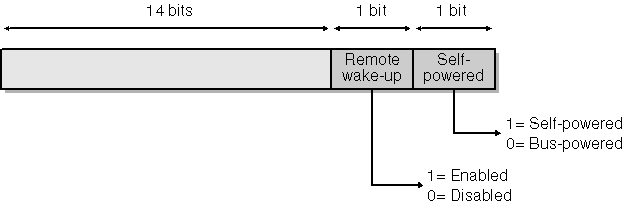
Figure 12-15. Bits in device status.
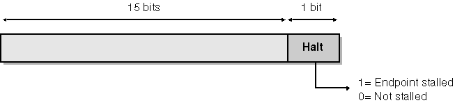
Figure 12-16. Bits in endpoint status.
Managing Isochronous Pipes
The purpose of an isochronous pipe is to allow the host and the device to exchange time-critical data with guaranteed regularity. The bus driver will devote up to 80 percent of the bus bandwidth to isochronous and interrupt transfers. What this means is that every 125-ms microframe will include reserved time slots long enough to accommodate maximum-size transfers to or from each of the isochronous and interrupt endpoints that are currently active. Figure 12-17 illustrates this concept for three different devices. Devices A and B each have an isochronous endpoint, for which a fixed and relatively large amount of time is reserved in every microframe. Device C has an interrupt endpoint whose polling frequency is once every two microframes; it has a reservation for a small portion of every second microframe. During microframes that don t include a poll of Device C s interrupt endpoint, additional bandwidth is available, perhaps for bulk transfers or other purposes.
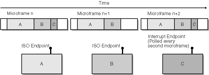
Figure 12-17. Allocation of bandwidth to isochronous and interrupt endpoints.
Reserving Bandwidth
The bus driver reserves bandwidth for you when you enable an interface by examining the endpoint descriptors that are part of the interface. Reserving bandwidth is just like buying a theater ticket, though: you don t get a refund if you don t use the space. Consequently, it s important to enable an interface that contains an isochronous endpoint only when you ll be using the bandwidth you thereby reserve, and it s important that the endpoint s declared maximum transfer size be approximately the amount you intend to use. Normally, a device with isochronous capability has a default interface that doesn t have any isochronous or interrupt endpoints. When you know you re about to access that capability, you enable an alternate setting of the same interface that does have the isochronous or interrupt endpoints.
An example will clarify the mechanics of reserving bandwidth. The USBISO sample in the companion content has an interface with a default and an alternate setting. The default setting has no endpoints. The alternate setting has an isochronous endpoint with a maximum transfer size of 256 bytes. See Figure 12-18.
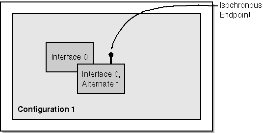
Figure 12-18. Descriptor structure for the USBISO device.
At StartDevice time, we select a configuration based on the default interface. Since the default interface doesn t have an isochronous or interrupt endpoint in it, we don t reserve any bandwidth just yet. When someone opens a handle to the device, however, we invoke the following SelectAlternateInterface helper function to switch to the alternate setting for our interface. (Again, I ve omitted the error checking.)
NTSTATUS SelectAlternateInterface(PDEVICE_OBJECT fdo) { PDEVICE_EXTENSION pdx = (PDEVICE_EXTENSION) fdo->DeviceExtension;
PUSB_INTERFACE_DESCRIPTOR pid = USBD_ParseConfigurationDescriptorEx(pdx->pcd, pdx->pcd, 0, 1, -1, -1, -1); ULONG npipes = pid->bNumEndpoints;
ULONG size = GET_SELECT_INTERFACE_REQUEST_SIZE(npipes); PURB urb = (PURB) ExAllocatePool(NonPagedPool, size); RtlZeroMemory(urb, size); 
UsbBuildSelectInterfaceRequest(urb, size, pdx->hconfig, 0, 1); urb->UrbSelectInterface.Interface.Length = GET_USBD_INTERFACE_SIZE(npipes); urb->UrbSelectInterface.Interface.Pipes[0].MaximumTransferSize = PAGE_SIZE;
NTSTATUS status = SendAwaitUrb(fdo, &urb); 
if (NT_SUCCESS(status)) { pdx->hinpipe = urb.UrbSelectInterface.Interface.Pipes[0].PipeHandle; status = STATUS_SUCCESS; } ExFreePool(urb); return status; } -
Before we can allocate space for the URB, we need to know how many pipe descriptors it will contain. The most common way to find this number is to go back to the grand unified configuration descriptor and find the descriptor for interface 0, alternate setting 1. That descriptor contains a count of endpoints, which is the same as the number of pipes that we re about to open.
-
GET_SELECT_INTERFACE_REQUEST_SIZE calculates the number of bytes needed to hold a select interface request that will open the specified number of pipes. We can then allocate memory for the URB and initialize it to 0. The real code sample in the companion content checks to make sure that the call to ExAllocatePool succeeded, by the way.
-
Here we build a URB to select alternate setting 1 (the last argument) of interface number 0 (the next-to-last argument).
-
We must do these two additional initialization steps to finish setting up the URB. Failing to set the interface information structure s length earns you a STATUS_BUFFER_TOO_SMALL failure right away. Failing to set the MaximumTransferSize fields of the pipe descriptors earns you a STATUS_INVALID_PARAMETER when you try to read or write the pipe.
-
When we submit this URB, the parent driver automatically closes the current setting of this interface, including all of its endpoints. Then the parent driver tells the device to enable the alternate setting, and it creates pipe descriptors for the endpoints that are part of the alternate setting. If opening the new interface fails for some reason, the parent driver reopens the previous interface, and all your previous interface and pipe handles remain valid.
-
My SendAwaitUrb helper function simply returns an error if it s unable to select the one and only alternate setting for this interface. I ll have a bit more to say about how you should handle errors after this numbered list.
-
In addition to selecting the new interface at the device level, the parent driver also creates an array of pipe descriptors from which we can extract handles for later use.
The select interface call might fail because not enough free bandwidth exists to accommodate our endpoint. We find out about the failure by examining the URB status:
if (URB_STATUS(&urb) == USBD_STATUS_NO_BANDWIDTH)
Dealing with lack of bandwidth poses a bit of a problem. The operating system doesn t currently provide a convenient way for competing drivers to negotiate a fair allocation. Neither does it provide for any sort of notification that some other driver has failed to acquire needed bandwidth so that we might give up some of ours. In this state of affairs, therefore, you have two basic choices. One choice is to provide multiple alternate interface settings, each of which has a different maximum transfer size for its isochronous endpoint or endpoints. When you detect an allocation failure, you can try to select progressively less demanding settings until you finally succeed.
A savvy end user who s able to launch the Windows XP Device Manager applet can display a property page for the USB host controller see Figure 12-19 that displays information about the current allocation of bandwidth. Double-clicking one of the devices listed in the page brings up the property display for the device in question. A well-crafted page can perhaps communicate with the associated device driver to scale back its demand for bandwidth. This whole area seems ripe for a more automatic Microsoft-driven solution, though.
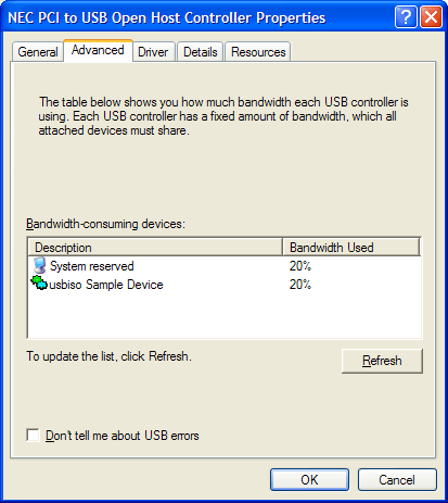
Figure 12-19. A property page for the USB host controller.
Your other choice for handling lack of bandwidth is to allow an IRP to fail in such a way that an application can alert the end user to the problem. Perhaps the end user can unplug something so that your device can be accommodated. This is the option I chose in the USBISO sample except that I didn t bother to put code in the test application that would respond to a bandwidth allocation failure TEST.EXE will just fail. To adopt this option, you need to know how the failure shows up back in user mode. If the URB fails with USBD_STATUS_NO_BANDWIDTH, the NTSTATUS code you get back from the internal control IRP is STATUS_DEVICE_DATA_ERROR, which isn t very specific. An application call to GetLastError will retrieve ERROR_CRC as the error code. There s no easy way for an application to discover that the real cause of the error is a lack of bandwidth, unfortunately. If you re interested in diving down this particular rat hole to reach a conclusion, read the sidebar.
How an Application Discovers You re out of Bandwidth
Suppose you do what USBISO does and try to select the high-bandwidth alternate interface when you receive an IRP_MJ_CREATE. Further suppose you complete the IRP with the status code you get back when there s not enough bandwidth namely, STATUS_DEVICE_DATA_ERROR. Your application caller will eventually see ERROR_CRC, as I said in the main text. What now? The application can t send you an IOCTL to find out the real cause of the error because it doesn t have a handle to your device. You allowed the IRP_MJ_CREATE to fail, remember? So maybe you need to have a way for people to open handles to your device that doesn t try to reserve bandwidth. Then you need some other way for an application to ask for bandwidth, perhaps by means of an IOCTL operation. Or perhaps your application just interprets ERROR_CRC from a call to CreateFile as meaning there s no bandwidth. Actual data errors are pretty unlikely, after all, so that interpretation would be correct much of the time.But the best solution would be a specific NTSTATUS code and matching Win32 error code that mean no bandwidth. Keep your eyes on NTSTATUS.H and WINERROR.H for future developments.
USBISO performs the converse operation of selecting the original default interface when it receives the IRP_MJ_CLOSE for the last remaining open handle. That operation entails issuing another select interface URB, but with the value 0 for the alternate interface index.
Initiating a Series of Isochronous Transfers
You can use an isochronous pipe either to read or write data in discrete chunks or to provide or consume data in a continuous stream. Data streaming is probably the most frequent occupation for an isochronous pipe, actually. But in addition to understanding the mechanics of working with the USB bus driver, you must understand and solve additional problems related to data buffering, rate matching, and so on if you want to operate a streaming pipe. The kernel-streaming component of the operating system deals with all these additional problems. Unfortunately, we didn t have time to include a chapter on kernel streaming in this book, even in the second edition. I m therefore going to show you only how to program a discrete transfer over an isochronous pipe.
To read from or write to an isochronous pipe, you ll of course use a URB with the appropriate function code. But there are a few wrinkles that you haven t seen yet associated with creating and submitting the isochronous URB. First, you must be aware of how the device will break up a transfer into packets. In general, the device is free to accept or deliver any amount of data less than the endpoint s declared maximum. (Any leftover bandwidth on the bus simply won t be used.) The packet size the device will use doesn t have any other necessary relationship with the endpoint maximum, with the maximum amount of data you said you d transfer in a URB, or with the amount of data the device and the application can exchange in a series of transactions. The firmware for the USBISO device, for example, works with 16-byte packets, even though the isochronous endpoint in question can handle up to 256 bytes per frame, according to its descriptor. You must have a priori knowledge of how big these packets will be before you construct a URB because the URB must include an array of descriptors for each packet that will be exchanged, and each of these descriptors must indicate how big the packet will be.
In an impractical simple situation, you can allocate an isochronous URB in the following way:
ULONG length = MmGetMdlByteCount(Irp->MdlAddress); ULONG packsize = 16; // a constant in USBISO ULONG npackets = (length + packsize - 1) / packsize; ASSERT(npackets <= 255); ULONG size = GET_ISO_URB_SIZE(npackets); PURB urb = (PURB) ExAllocatePool(NonPagedPool, size); RtlZeroMemory(urb, size);
The key step in this fragment is the use of the GET_ISO_URB_SIZE macro to calculate the total size needed for an isochronous URB to transfer a given number of data packets. A single URB can accommodate a maximum of 255 isochronous packets (1024 in the case of a high-speed device), by the way, which is why I put the ASSERT statement in this code. Limiting the application to just 255 packets is not practical, as I said, so we will do something more complex in the real USBISO sample driver. For the time being, though, I just want to describe the mechanics of building a single URB for an isochronous (ISO) transfer.
NOTE
As indicated in the text, a single URB can transfer up to 255 packets to a full-speed device in the course of that many 1-ms frames. For a high-speed device, the maximum packet count is 1024 in the course of up to 128 1-ms frames. Furthermore, each URB should contain a multiple of 8 packets. This makes sense because there are 8 microframes in one frame.
There being no UsbBuildXxxRequest macro for building an isochronous URB, we go on to initialize the new URB by hand:
urb->UrbIsochronousTransfer.Hdr.Length = (USHORT) size; urb->UrbIsochronousTransfer.Hdr.Function = URB_FUNCTION_ISOCH_TRANSFER; urb->UrbIsochronousTransfer.PipeHandle = pdx->hinpipe; urb->UrbIsochronousTransfer.TransferFlags = USBD_TRANSFER_DIRECTION_IN USBD_SHORT_TRANSFER_OK; urb->UrbIsochronousTransfer.TransferBufferLength = length; urb->UrbIsochronousTransfer.TransferBufferMDL = Irp->MdlAddress; urb->UrbIsochronousTransfer.NumberOfPackets = npackets; urb->UrbIsochronousTransfer.StartFrame = frame; for (ULONG i = 0; i < npackets; ++i, length -= packsize) { urb->UrbIsochronousTransfer.IsoPacket[i].Offset = i * packsize; } The array of packet descriptors collectively describes the entire data buffer that we ll read in to or write out from. This buffer has to be contiguous in virtual memory, which basically means that you need a single MDL to describe it. It would be pretty hard to violate this rule. Reinforcing the idea of contiguity, each packet descriptor contains just the offset and the length for a portion of the entire buffer and not an actual pointer. The host controller driver is responsible for setting the length; you re responsible for setting the offset.
The second wrinkle with starting an isochronous transfer involves timing. USB uniquely identifies each frame or microframe, as the case may be, with an ever-increasing number. It s sometimes important that a transfer begin in a specific frame. The parent driver allows you to indicate this fact by explicitly setting the StartFrame field of the URB. USBISO doesn t depend on timing, however. You might therefore think it could set the USBD_START_ISO_TRANSFER_ASAP flag to indicate that the transfer should be started as soon as possible. Setting the flag would, in fact, work in versions of Windows prior to Windows XP. Unfortunately, Windows XP introduced a bug such that an ASAP transfer that would start more than 256 frames in the future gets scheduled right away. In the context of this sample, this bug causes the packets to be transferred 0, 256, 2, 3, . To avoid this problem, I revised USBISO to use a specific frame number calculated as follows:
ULONG frame = GetCurrentFrame(pdx) + 2;
Where the GetCurrentFrame function is this one:
ULONG GetCurrentFrame(PDEVICE_EXTENSION pdx) { URB urb; urb.UrbGetCurrentFrameNumber.Hdr.Length = sizeof(struct _URB_GET_CURRENT_FRAME_NUMBER); urb.UrbGetCurrentFrameNumber.Hdr.Function = URB_FUNCTION_GET_CURRENT_FRAME_NUMBER; NTSTATUS status = SendAwaitUrb(pdx->DeviceObject, &urb); if (!NT_SUCCESS(status)) return 0; return urb.UrbGetCurrentFrameNumber.FrameNumber; } I don t necessarily recommend that you always get the current frame number for an ISO transfer. USBISO has to do so because it s reading 256 packets. In a more usual situation, you have a streaming driver that issues a few read or write URBs for just a few packets, and you re continually recycling these URBs as time goes on. You won t run afoul of the 256-frames-in-the-future problem in that case and can just use the USBD_START_ISO_TRANSFER_ASAP flag.
The final wrinkle in isochronous processing has to do with how the transfer ends. The URB itself will succeed overall, even though one or more packets had data errors. The URB has a field named ErrorCount that indicates how many packets encountered errors. If this ends up nonzero, you can loop through the packet descriptors to examine their individual status fields.
Achieving Acceptable Performance
Achieving acceptable performance with isochronous transfers will be something of a challenge in a streaming environment or in a situation in which you have a multistage transfer to orchestrate. One strategy is to arrange to run in a real-time thread at DISPATCH_LEVEL and submit URBs nearly directly to the bus driver via the SubmitIsoOutUrb function in the bus driver s direct-call interface. If you re doing input operations, however, or if you need to support platforms earlier than Windows XP, you need to submit multiple URBs, such that the bus driver has one to work with as soon as an earlier one finishes.
The USBISO sample in the companion content illustrates how to manage a large block transfer using multiple subsidiary URBs. The basic idea behind USBISO s read/write logic is to have the completion routine for subsidiary IRPs complete the main read/write IRP when the last subsidiary IRP finishes. To make this idea work, I declared the following special-purpose context structure:
typedef struct _RWCONTEXT { PDEVICE_EXTENSION pdx; PIRP mainirp; NTSTATUS status; ULONG numxfer; ULONG numirps; LONG numpending; LONG refcnt; struct { PIRP irp; PURB urb; PMDL mdl; } sub[1]; } RWCONTEXT, *PRWCONTEXT; The dispatch routine for IRP_MJ_READ USBISO doesn t handle IRP_MJ_WRITE requests calculates the number of subsidiary IRPs required for the complete transfer and allocates one of these context structures, as follows:
ULONG packsize = 16; ULONG segsize = USBD_DEFAULT_MAXIMUM_TRANSFER_SIZE; if (segsize / packsize > 255) segsize = 255 * packsize; ULONG numirps = (length + segsize - 1); ULONG ctxsize = sizeof(RWCONTEXT) + (numirps - 1) * sizeof(((PRWCONTEXT) 0)->sub); PRWCONTEXT ctx = (PRWCONTEXT) ExAllocatePool(NonPagedPool, ctxsize); RtlZeroMemory(ctx, ctxsize); ctx->numirps = ctx->numpending = numirps; ctx->pdx = pdx; ctx->mainirp = Irp; ctx->refcnt = 2; Irp->Tail.Overlay.DriverContext[0] = (PVOID) ctx;
I ll explain the purpose of the last two statements in this sequence when I discuss USBISO s cancellation logic in the Handling Cancellation of the Main IRP section. We now perform a loop to construct numirpsIRP_MJ_INTERNAL_DEVICE_CONTROL requests. At each iteration of the loop, we call IoAllocateIrp to create an IRP with one more stack location than is required by the device object immediately under us. We also allocate a URB to control one stage of the transfer and a partial MDL to describe the current stage s portion of the main I/O buffer. We record the address of the IRP, the URB, and the partial MDL in an element of the RWCONTEXT structure s sub array. We initialize the URB in the same way as I showed you earlier. Then we initialize the subsidiary IRP s first two I/O stack locations, as follows:
IoSetNextIrpStackLocation(subirp); PIO_STACK_LOCATION stack = IoGetCurrentIrpStackLocation(subirp); stack->DeviceObject = fdo; stack->Parameters.Others.Argument1 = (PVOID) urb; stack->Parameters.Others.Argument2 = (PVOID) mdl; stack = IoGetNextIrpStackLocation(subirp); stack->MajorFunction = IRP_MJ_INTERNAL_DEVICE_CONTROL; stack->Parameters.Others.Argument1 = (PVOID) urb; stack->Parameters.DeviceIoControl.IoControlCode = IOCTL_INTERNAL_USB_SUBMIT_URB; IoSetCompletionRoutine(subirp, (PIO_COMPLETION_ROUTINE) OnStageComplete, (PVOID) ctx, TRUE, TRUE, TRUE);
The first stack location is for use by the OnStageComplete completion routine we install. The second is for use by the lower-level driver.
Once we ve built all the IRPs and URBs, it s time to submit them to the bus driver. Before we do so, however, it s prudent to check whether the main IRP has been cancelled, and it s necessary to install a completion routine for the main IRP. The logic at the end of the dispatch routine looks like the following code:
IoSetCancelRoutine(Irp, OnCancelReadWrite); if (Irp->Cancel) { status = STATUS_CANCELLED; if (IoSetCancelRoutine(Irp, NULL)) ctx->refcnt; } else status = STATUS_SUCCESS; IoSetCompletionRoutine(Irp, (PIO_COMPLETION_ROUTINE) OnReadWriteComplete, (PVOID) ctx, TRUE, TRUE, TRUE); IoMarkIrpPending(Irp); IoSetNextIrpStackLocation(Irp); if (!NT_SUCCESS(status)) { for (i = 0; i < numirps; ++i) { if (ctx->sub[i].urb) ExFreePool(ctx->sub[i].urb); if (ctx->sub[i].mdl) IoFreeMdl(ctx->sub[i].mdl); } CompleteRequest(Irp, status, 0); return STATUS_PENDING; } for (i = 0; i < numirps; ++i) IoCallDriver(pdx->LowerDeviceObject, ctx->sub[i].irp); return STATUS_PENDING;
Handling Cancellation of the Main IRP
To explain the two completion routines that I m using in this example that is, OnReadWriteComplete for the main IRP and OnStageComplete for each subsidiary IRP I need to explain how USBISO handles cancellation of the main IRP. Cancellation is a concern because we ve submitted a potentially large number of subsidiary IRPs that might take some time to finish. We can t complete the main IRP until all of the subsidiary IRPs complete. We should, therefore, provide a way to cancel the main IRP and all outstanding subsidiary IRPs.
I m sure you recall from Chapter 5 that IRP cancellation implicates a number of knotty synchronization issues. If anything, the situation in this driver is worse than usual.
USBISO s cancellation logic is complicated by the fact that we can t control the timing of calls to the subsidiary IRPs completion routine those IRPs are owned by the bus driver once we submit them. Suppose you wrote the following cancel routine:
VOID OnCancelReadWrite(PDEVICE_OBJECT fdo, PIRP Irp) { IoReleaseCancelSpinLock(Irp->CancelIrql);
PRWCONTEXT ctx = (PRWCONTEXT) Irp->Tail.Overlay.DriverContext[0];
for (ULONG i = 0; i < ctx->numirps; ++i) IoCancelIrp(ctx->sub[i].irp); <additional steps> } -
We saved the address of the RWCONTEXT structure in the DriverContext area of the IRP precisely so that we could retrieve it here. DriverContext is ours to use so long as we own the IRP. Since we returned STATUS_PENDING from the dispatch routine, we never relinquished ownership.
-
Here we cancel all the subsidiary IRPs. If a subsidiary IRP has already completed or is currently active on the device, the corresponding call to IoCancelIrp won t do anything. If a subsidiary IRP is still in the host controller driver s queue, the host controller driver s cancel routine will run and complete the subsidiary IRP. In all three cases, therefore, we can be sure that all subsidiary IRPs will be completed sometime soon.
This version of OnCancelReadWrite is almost complete, by the way, but it needs an additional step that I ll show you after I ve explained the synchronization problem we need to solve. I can illustrate the problem by showing the completion routines we ll use with two naive mistakes built in. Here s the completion routine for one stage of the total transfer:
NTSTATUS OnStageComplete(PDEVICE_OBJECT fdo, PIRP subirp, PRWCONTEXT ctx) {
PIO_STACK_LOCATION stack = IoGetCurrentIrpStackLocation(Irp); PIRP mainirp = ctx->mainirp; PURB urb = (PURB) stack->Parameters.Others.Argument1; if (NT_SUCCESS(Irp->IoStatus.Status)) {
InterlockedExchangeAdd((PLONG) &ctx->numxfer, (LONG) urb->UrbIsochronousTransfer.TransferBufferLength); } else
ctx->status = Irp->IoStatus.Status;
ExFreePool(urb); IoFreeMdl((PMDL) stack->Parameters.Others.Argument2);
IoFreeIrp(subirp); // <== don't do this if (InterlockedDecrement(&ctx->numpending) == 0) { IoSetCancelRoutine(mainirp, NULL); // <== also needs some work mainirp->IoStatus.Status = ctx->status;
IoCompleteRequest(mainirp, IO_NO_INCREMENT); } return STATUS_MORE_PROCESSING_REQUIRED; } -
This stack location is the extra one that the dispatch routine allocated. We need the address of the URB for this stage, and the stack was the most convenient place to save that address.
-
When a stage completes normally, we update the cumulative transfer count for the main IRP here. The final value of numxfer will end up in the main IRP s IoStatus.Information field.
-
We initialized status to STATUS_SUCCESS by zeroing the entire context structure. If any stage completes with an error, this statement will record the error status. The final value will end up in the main IRP s IoStatus.Status field.
-
We no longer need the URB or the partial MDL for this stage, so we release the memory they occupied here.
-
This call to IoFreeIrp is the naive part of this completion routine, as I ll explain shortly.
-
When the last stage completes, we ll also complete the main IRP. Once we ve submitted the subsidiary IRPs, this is the only place where we complete the main IRP, so we can be sure that the main IRP pointer is valid.
Here s the naive version of the completion routine for the main IRP:
NTSTATUS OnReadWriteComplete(PDEVICE_OBJECT fdo, PIRP Irp, PRWCONTEXT ctx) { PDEVICE_EXTENSION pdx = (PDEVICE_EXTENSION) ctx->pdx;
if (Irp->Cancel) Irp->IoStatus.Status = STATUS_CANCELLED; else if (NT_SUCCESS(Irp->IoStatus.Status)) Irp->IoStatus.Information = ctx->numxfer;
ExFreePool(ctx); // <== don't do this return STATUS_SUCCESS; } -
If someone tried to cancel the main IRP, this statement will set the corresponding ending status.
-
Releasing the context structure s memory is a problem, as I ll explain.
I ve been building up to a big and dramatic expos of a synchronization problem associated with IRP cancellation, and here it finally is: Suppose our cancel routine gets called after one or more of the calls to IoFreeIrp has already happened inside OnStageComplete. You can see that we might call IoCancelIrp with an invalid pointer in such a case. Or suppose the cancel routine gets called more or less simultaneously with OnReadWriteComplete. In that case, we might have the cancel routine accessing the context structure after it gets deleted.
You might attempt to solve these problems with various subterfuges. Can OnStageComplete nullify the appropriate subsidiary IRP pointer in the context structure, and can OnCancelReadWrite check before calling IoCancelIrp? (Yes, but there s still no way to guarantee that the call to IoFreeIrp doesn t squeeze in between whatever test OnCancelReadWrite makes and the moment when IoCancelIrp is finally done modifying the cancel-related fields of the IRP.) Can you protect the various cleanup steps with a spin lock? (That s a horrible idea because you ll be holding the spin lock across calls to time-consuming functions.) Can you take advantage of knowing that the current release of Windows XP always cleans up completed IRPs in an asynchronous procedure call (APC) routine? (No, for the reasons I discussed back in Chapter 5.)
I struggled long and hard with this problem before inspiration finally struck. Why not, I finally realized, protect the context structure and the subsidiary IRP pointers with a reference count so that both the cancel routine and the main completion routines can share responsibility for cleaning them up? That s what I ended up doing. I put a reference count field (refcnt) in the context structure and initialized it to the value 2. One reference is for the cancel routine; the other is for the main completion routine. I wrote the following helper function to release the memory objects that are the source of the problem:
BOOLEAN DestroyContextStructure(PRWCONTEXT ctx) { if (InterlockedDecrement(&ctx->refcnt) > 0) return FALSE; for (ULONG i = 0; i < ctx->numirps; ++i) if (ctx->sub[i].irp) IoFreeIrp(ctx->sub[i].irp); ExFreePool(ctx); return TRUE; } I call this routine at the end of the cancel routine:
VOID OnCancelReadWrite(PDEVICE_OBJECT fdo, PIRP Irp) { IoReleaseCancelSpinLock(Irp->CancelIrql); PRWCONTEXT ctx = (PRWCONTEXT) Irp->Tail.Overlay.DriverContext[0]; for (ULONG i = 0; i < ctx->numirps; ++i) IoCancelIrp(ctx->sub[i].irp); PDEVICE_EXTENSION pdx = ctx->pdx; if (DestroyContextStructure(ctx)) { CompleteRequest(Irp, STATUS_CANCELLED, 0); IoReleaseRemoveLock(&pdx->RemoveLock, Irp); } } I omitted the call to IoFreeIrp in the stage completion routine and added one more line of code to decrement the reference count once it s certain that the cancel routine hasn t been, and can no longer, be called:
NTSTATUS OnStageComplete(PDEVICE_OBJECT fdo, PIRP subirp, PRWCONTEXT ctx) { PIO_STACK_LOCATION stack = IoGetCurrentIrpStackLocation(Irp); PIRP mainirp = ctx->mainirp; PURB urb = (PURB) stack->Parameters.Others.Argument1; if (NT_SUCCESS(Irp->IoStatus.Status)) ctx->numxfer += urb->UrbIsochronousTransfer.TransferBufferLength; else ctx->status = Irp->IoStatus.Status; ExFreePool(urb); IoFreeMdl((PMDL) stack->Parameters.Others.Argument2); if (InterlockedDecrement(&ctx->numpending) == 0) { if (IoSetCancelRoutine(mainirp, NULL)) InterlockedDecrement(&ctx->refcnt); mainirp->IoStatus.Status = ctx->status; IoCompleteRequest(mainirp, IO_NO_INCREMENT); } return STATUS_MORE_PROCESSING_REQUIRED; } Recall that IoSetCancelRoutine returns the previous value of the cancel pointer. If that s NULL, the cancel routine has already been called and will call DestroyContextStructure. If that s not NULL, however, it will no longer be possible for the cancel routine ever to be called, and we must use up the cancel routine s claim on the context structure.
I also replaced the unconditional call to ExFreePool in the main completion routine with a call to DestroyContextStructure:
NTSTATUS OnReadWriteComplete(PDEVICE_OBJECT fdo, PIRP Irp, PRWCONTEXT ctx) { PDEVICE_EXTENSION pdx = (PDEVICE_EXTENSION) ctx->pdx; if (Irp->Cancel) Irp->IoStatus.Status = STATUS_CANCELLED; else if (NT_SUCCESS(Irp->IoStatus.Status)) Irp->IoStatus.Information = ctx->numxfer; if (DestroyContextStructure(ctx)) { IoReleaseRemoveLock(&pdx->RemoveLock, Irp); return STATUS_SUCCESS; } else return STATUS_MORE_PROCESSING_REQUIRED; } Here s how this extra logic works. If the cancel routine ever gets called, it will run through the context structure calling IoCancelIrp for each of the subsidiary IRPs. Even if all of them have already completed, these calls will still be safe because we won t have called IoFreeIrp yet. The reference to the context structure will also be safe because we won t have called ExFreePool yet. The cancel routine finishes up by calling DestroyContextStructure, which will decrement the reference counter. If the main completion routine hasn t run yet, DestroyContextStructure will return FALSE, whereupon the cancel routine will return. The context structure still exists at this point, which is good because the main completion routine will reference it soon. The completion routine s eventual call to DestroyContextStructure will release the subsidiary IRPs and the context structure itself. The completion routine will then return STATUS_SUCCESS to allow the main IRP to finish completing.
Suppose calls to the cancel and main completion routines happen in the other order. In that case, OnReadWriteComplete s call to DestroyContextStructure will simply decrement the reference count and return FALSE, whereupon OnReadWriteComplete will return STATUS_MORE_PROCESSING_REQUIRED. The context structure still exists. We can also be sure that we still own the IRP and the DriverContext field from which the cancel routine will fetch the context pointer. The cancel routine s call to DestroyContextStructure will, however, reduce the reference count to 0, release the memory, and return TRUE. The cancel routine will then release the remove lock and call IoCompleteRequest for the main IRP. That adds up to two calls to IoCompleteRequest for the same IRP. You know that you re not allowed to complete the same IRP twice, but the prohibition is not against calling IoCompleteRequest twice per se. If the first invocation of IoCompleteRequest results in calling a completion routine that returns STATUS_MORE_PROCESSING_REQUIRED, a subsequent, duplicate call is perfectly OK.
The only remaining case in this analysis occurs when the cancel routine never gets called at all. This is, of course, the normal case because IRPs don t usually get cancelled. We discover this fact when we call IoSetCancelRoutine in preparation for completing the main IRP. If IoSetCancelRoutine returns a non-NULL value, we know that IoCancelIrp has not yet been called for the main IRP. (Had it been, the cancel pointer would already be NULL, and IoSetCancelRoutine would have returned NULL.) Furthermore, we know that our own cancel routine can now never be called and will therefore not have a chance to reduce the reference count. Consequently, we reduce the reference count by hand so that OnReadWriteComplete s call to DestroyContextStructure will release the memory.
Where s the Synchronization?
You ll notice that I didn t use a spin lock to guard the code I just showed you for testing for cancellation inside the dispatch routine. Synchronization between that code and some hypothetical caller of IoCancelIrp is implicit in the facts that IoSetCancelRoutine is an interlocked exchange operation and that IoCancelIrp sets the Cancel flag before calling IoSetCancelRoutine. Refer to the discussion in Chapter 5 for a sketch of how IoCancelIrp works.Our dispatch routine s first call to IoSetCancelRoutine might occur after IoCancelIrp sets the Cancel flag but before IoCancelIrp does its own call to IoSetCancelRoutine. Our dispatch routine will see that the Cancel flag is set and make a second call to IoSetCancelRoutine. If this second call happens to precede IoCancelIrp s call to IoSetCancelRoutine, the cancel routine won t be called. We ll also decrement the reference count on the context structure so that it gets released on the first call to DestroyContextStructure.
If our dispatch routine s second call to IoSetCancelRoutine follows IoCancelIrp s, we won t decrement the reference count. Either the cancel routine or the completion routine will end up releasing the context structure.
If our dispatch routine tests the Cancel flag before IoCancelIrp sets it, or if IoCancelIrp has never even been called for this IRP, we ll go ahead and start the subsidiary IRPs. If IoCancelIrp was called in the distant past before we installed a cancel routine, it will have simply set the Cancel flag and returned. What happens after that is just the same as when our dispatch routine nullifies the cancel pointer before IoCancelIrp calls IoSetCancelRoutine.
So you see, you don t always need a spin lock to give you multiprocessor safety: sometimes an atomic interlocked operation will do the trick by itself.
Associated IRPs?
At first blush, IoMakeAssociatedIrp looks like an alternative way to create the subsidiary IRPs that USBISO needs. The idea behind IoMakeAssociated Irp is that you can create a number of associated IRPs to fulfill a master IRP. When the last associated IRP completes, the I/O Manager automatically completes the master IRP.Unfortunately, associated IRPs aren t a good way to solve any of the problems that USBISO grapples with. Most important, WDM drivers aren t supposed to use IoMakeAssociatedIrp. Indeed, the completion logic for associated IRPs is incorrect in Windows 98/Me it doesn t call any completion routines for the master IRP when the last associated IRP finishes. Even in Windows XP, however, the I/O Manager won t cancel associated IRPs when the master IRP is cancelled. Furthermore, the call to IoFreeIrp for an associated IRP occurs inside IoCompleteRequest, in whatever thread context happens to be current. This fact makes it harder to safely cancel the associated IRPs.
Idle Power Management for USB Devices
I m sure you ll agree with me that power management in a WDM driver isn t complicated enough. (Not!) In Chapter 8, I discussed strategies for keeping a device in a low-power state when it s not in use, whatever in use means for your particular device. Beginning with Windows XP, there is a special protocol for USB devices called selective suspend. In this final section of the chapter, I ll describe the mechanics a function driver should use to implement this protocol.
NOTE
The Chapter 8 WAKEUP sample in the companion content contains the code discussed in this section.
The selective suspend feature introduced in Windows XP solves a wake-up problem that arises in composite devices. Suppose you have a two-function device, with each function being managed by a separate function driver. Now suppose one of the function drivers issues both an IRP_MN_WAIT_WAKE and an IRP_MN_SET_POWER to put its interface in the D2 state, but the other function driver leaves its interface in the D0 state. The first function driver might be relying on a wake-up signal to repower its interface. If the physical device were not composite, the parent driver would have armed its wake-up feature and put it in D2. Resuming the device would then generate a wake-up signal, and the parent driver would complete the WAIT_WAKE.
But wake-up signaling doesn t happen in the composite device. The parent driver doesn t power down the real device (and doesn t arm its wake-up signaling) unless all function drivers independently ask to have their interfaces powered down. In the example I gave, only one out of two function drivers powered its interface down. Since the real device never suspends, it has no reason ever to generate a wake-up signal. The function driver for the interface that was supposed to have been suspended doesn t realize this, however, and is therefore not trying to communicate with the device. The end result is a dead function on the device.
Selective suspend provides coordination between the function drivers to solve the problem. Here s how this works. Instead of directly powering down its interface, a function driver issues an IOCTL to the parent driver. The import of the IOCTL is, I m ready to be suspended, and here s a function you can call so I can do that. When all function drivers for a particular composite device issue this IOCTL, the parent driver can call all of the callback routines. Each callback routine depowers its own interface. The parent driver then depowers the real device. A subsequent wake-up signal reactivates each function driver that issued an IRP_MN_WAIT_WAKE. Voil ! No more dead functions.
Most USB function drivers manage a single interface. You shouldn t assume that a particular interface will never be part of a composite device, and you should assume that function drivers for other interfaces on the same device will be relying on wake-up signalling even if you don t. Therefore, you should follow the selective suspend protocol I m about to describe. If your driver happens to run on a platform earlier than Windows XP, you should disable your own wake-up and automatic-suspend features by default. You can provide instructions to allow the end user to enable one or both of such features in situations in which you won t trip on the dead-interface problem.
Note that even if your driver manages all the interfaces on a particular device, you should invoke the selective suspend protocol because the Microsoft drivers also rely on it to help them compensate for hardware bugs in various chip sets.
The first thing you need to do is declare some additional members in your device extension structure:
typedef struct _DEVICE_EXTENSION { PIRP SuspendIrp; LONG SuspendIrpCancelled; USB_IDLE_CALLBACK_INFO cbinfo; } DEVICE_EXTENSION, *PDEVICE_EXTENSION; Then, when you decide it s time to put your device in a low-power state because you consider it to be idle, you issue an internal control request to your parent driver to register a callback routine (SelectiveSuspendCallback):
NTSTATUS IssueSelectiveSuspendRequest(PDEVICE_EXTENSION pdx) { PIRP Irp = IoAllocateIrp(pdx->LowerDeviceObject->StackSize, FALSE); pdx->cbinfo.IdleCallback = (USB_IDLE_CALLBACK) SelectiveSuspendCallback; pdx->cbinfo.IdleContext = (PVOID) pdx; PIO_STACK_LOCATION stack = IoGetNextIrpStackLocation(Irp); stack->MajorFunction = IRP_MJ_INTERNAL_DEVICE_CONTROL; stack->Parameters.DeviceIoControl.IoControlCode = IOCTL_INTERNAL_USB_SUBMIT_IDLE_NOTIFICATION; stack->Parameters.DeviceIoControl.Type3InputBuffer = &pdx->cbinfo; pdx->SuspendIrp = Irp; pdx->SuspendIrpCancelled = 0; IoSetCompletionRoutine(Irp, (PIO_COMPLETION_ROUTINE) SelectiveSuspendCompletionRoutine, (PVOID) pdx, TRUE, TRUE, TRUE); IoCallDriver(pdx->LowerDeviceObject, Irp); return STATUS_SUCCESS; } You use an asynchronous IRP for this control operation because it might remain outstanding for a long period, and you might, therefore, need to cancel it. I followed my own advice from Chapter 5 in orchestrating the cancellation and completion routines:
VOID CancelSelectiveSuspend(PDEVICE_EXTENSION pdx) { PIRP Irp = (PIRP) InterlockedExchangePointer( (PVOID*) &pdx->SuspendIrp, NULL); if (Irp) { IoCancelIrp(Irp); if (InterlockedExchange(&pdx->SuspendIrpCancelled, 1)) IoFreeIrp(Irp); } } NTSTATUS SelectiveSuspendCompletionRoutine(PDEVICE_OBJECT junk, PIRP Irp, PDEVICE_EXTENSION pdx) { NTSTATUS status = Irp->IoStatus.Status; if (InterlockedExchangePointer((PVOID*) &pdx->SuspendIrp, NULL) InterlockedExchange(&pdx->SuspendIrpCancelled, 1)) IoFreeIrp(Irp); if (!NT_SUCCESS(status) && status != STATUS_POWER_STATE_INVALID) GenericWakeupFromIdle(pdx->pgx, FALSE); return STATUS_MORE_PROCESSING_REQUIRED; } (I ll explain in a moment why there s a call to GenericWakeupFromIdle here.)
In a normal case, the parent driver pends the idle-notification IRP until all devices attached to the same hub ask to be idled. When that occurs, the parent driver calls the callback routine, whereupon you carry out two steps. First you make sure that your wake-up feature (if any) is armed and that a WAIT_WAKE request is outstanding. Second you request a power IRP to put your device in your desired low-power state. For example, in a driver that uses GENERIC.SYS for power management, your callback routine could be this simple:
VOID SelectiveSuspendCallback(PDEVICE_EXTENSION pdx) { GenericWakeupControl(pdx->pgx, ManageWaitWake); GenericIdleDevice(pdx->pgx, PowerDeviceD2, TRUE); } The TRUE argument to GenericIdleDevice makes the power operation synchronous, which is a requirement in this situation. In fact, returning from the callback routine before your device is in its low-power state would cause the parent driver to incorrectly believe you couldn t power down, whereupon the whole hub and all attached devices would stay powered.
If the parent driver allows the idle notification request to fail, your device may have ended up in a low-power state, and you should repower it from your completion routine hence the call to GenericWakeupFromIdle in the example. The only exception will be if the request completes with STATUS_POWER_STATE_INVALID, which happens if you put the device in the D3 state while the IRP is outstanding. That can happen, for example, if the system is hibernating.
Finally, don t forget to cancel your outstanding idle notification IRP at StopDevice time.
EAN: 2147483647
Pages: 119
- Chapter I e-Search: A Conceptual Framework of Online Consumer Behavior
- Chapter II Information Search on the Internet: A Causal Model
- Chapter IV How Consumers Think About Interactive Aspects of Web Advertising
- Chapter X Converting Browsers to Buyers: Key Considerations in Designing Business-to-Consumer Web Sites
- Chapter XVIII Web Systems Design, Litigation, and Online Consumer Behavior