Adding Tables to Your Drawing
One of the more common text- related tasks you'll do for your drawings is to create schedules, such as door and window schedules or parts schedules. Such schedules are tables used to provide more detailed information regarding the elements in your design.
In the past, AutoCAD users would use Mtext or Dtext to create the text for schedules, and then use line-drawing tools to create the " cells " of the schedule. AutoCAD 2005 offers Tables to help you generate schedules more quickly. Tables offer a way to automatically format the columns and rows of text in a way similar to spreadsheet programs.
Creating a Table
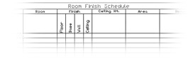
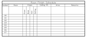
The first step in creating a table is to determine the number of rows and columns you'll want. Don't worry if you are not certain of the exact number of rows and columns; you can always add or subtract them at any time. In this exercise, you'll create a table that contains 12 rows and 9 columns, as shown in Figure 8.15.
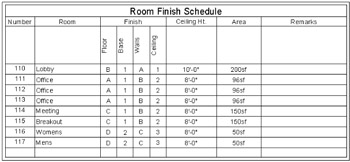
Figure 8.15: A sample table created with the Tables tool
Start by creating the basic table layout:
-
Choose File New and use the standard Acad.dwt drawing template.
-
 Click Table from the Draw toolbar, or select Draw Table from the menu bar. The Insert Table dialog box appears.
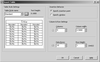
-
In the Column & Row Settings group , enter 9 for the columns and 12 for the rows.
-
Click OK. The dialog box closes , and you see the outline of a table follow your cursor.
-
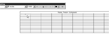
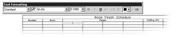
Position the table in the center of your drawing area and click to place the table. The table appears with a cursor in the top cell of the table. You also see the Text Formatting dialog box above the table.
-
Enter the name Room Finish Schedule and press
 . Notice that the cursor moves to the next cell.
 -
Click OK to exit the Text Formatting dialog box.
Adding Cell Text
You've just created a table and added a title. Notice that the table actually contains 14 rows, including the title row at the top and an additional row for the headings of each column. You can delete these additional rows if you don't need them, but for now, you'll start to add some text to the table:
-
Adjust your view so that the table fills most of the drawing area.
-
Double-click in the first cell at the top left, just below the Room Finish Schedule label. The cell turns gray, and the Text Formatting dialog box appears.
-
Enter the word Number for the room number column at the far left and then press the Tab key to advance to the next cell to the right.
-
Enter Room and press the Tab key again.
-
Enter Finish and press the Tab key four times to advance four columns. You do this because the Finish heading shown in Figure 8.15 has four columns under it: Floor, Base, Walls and Ceiling. In the next exercise, you'll learn how to format those four columns under the single heading.
-
Enter Ceiling Ht. and press the Tab key again.
-
Enter Area , press the Tab key, and enter Remarks .
-
Click OK in the Text Formatting dialog box to close it.
You have the column headings in place. Now you need to do a little extra formatting. In step 5, you left four cells blank because four of the columns will be combined under on heading. The Finish heading covers the Floor, Base, Walls, and Ceiling columns. Next you'll combine the blank headings with the Finish heading:
-
Click in the center of the cell with the Finish label to select it.
-
Shift+click in the third cell to the right of the Finish cell to select all four cells.
-
Right-click in the selected cells and select Merge Cells All. The four selected cells merge into a single cell with the word Finish.
Now you need to add the subheads under the Finish header:
-
Double-click in the leftmost cell below the Finish cell. The Text Formatting dialog box appears.
-
Enter Floor and press the Tab key.
-
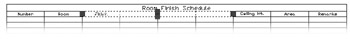
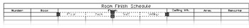
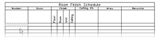
Enter the Base , Walls , and Ceiling text in each of the following columns as you have been doing. Remember that the Tab key advances you to the next cell to the right. Your table should look like Figure 8.16.
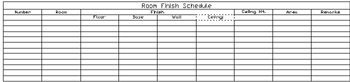
Figure 8.16: The table so far -
Click OK in the Text Formatting dialog box to close it.
Adjusting Table Text Orientation and Location
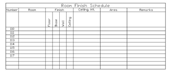
You now have the basic layout of the table, with one difference. The Floor, Base, Wall, and Ceiling labels you've just added are oriented horizontally, but you want them oriented vertically, as in Figure 8.15. The following steps will show you how to rotate a set of labels in a table so that they appear in the orientation you want:
-
Click in the cell labeled Floor to select it.
-
Shift+click in the cell labeled Ceiling to select all four of the cells below the Finish heading. Notice that the combined cells have four grips, one on each side of the group.
-
Click the grip at the bottom of the selected group and move it down about four rows. The entire row will become taller. This provides room for the text when you rotate it.
-
Right-click in the selected cells and select Properties in the shortcut menu to open the Properties palette.
-
In the Properties palette, click the Text Rotation option under the Content group.
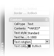
-
Click the drop-down list just to the left of the Text Rotation option and select 90. The text rotates into a vertical orientation.
With the text in this orientation, the columns are too wide, so you will want to change the cell width for the selected cells.
-
With the Properties palette still open, click the Cell Width option near the top of the palette and enter .65 for the cell-width value. The cells change to their new width.

-
For the final touch, you'll want to center the text in the cells. With the cells still selected, right-click in the selected cells and choose Cell Alignment Middle Left. The text become centered in the cells.
Tip You can also control the margin between the text and the cell border by using the Cell Margin options in the Properties palette. Select the entire table, right-click, and select Properties. At the Properties palette, click the Vertical Cell Margin option or the Horizontal Cell Margin option in the Table group.
In this last exercise, you learned how you can adjust the text orientation and cell width through the Properties palette. You can also adjust the width of multiple cells by adjusting the grip location. For example, instead of changing the cell width value in step 7, you could have moved the left or right grip of the selected group of cells.
Now continue to add text to the cells and adjust their sizes:
-
Double-click in the row immediately below the Floor cell, double-click the cell in the Number column to the far left. A text cursor appears in the cell, and the Text Formatting dialog box appears.
-
Enter 110 and press
. Notice that instead of advancing to the next cell to the right, you advance to the next cell below. -
Enter 111 and press
again. Continue to enter each room number in this way. When you've finished entering the room numbers , click OK in the Text Formatting dialog box to close it. Now you'll want to reduce the width of the column to fit the text a bit better.
-
Click in the cell with the Number text label. It's the first column heading in the table.
-
Shift+click in the bottom cell of the Number column to select the entire column.
-
Click the grip to the left of the column and move the grip to the right so the column width is similar to the width of the Room column. You can zoom in on the column to allow more control over the positioning of the grip.
-
Press Esc to exit the selection and view your table so far.
Now suppose you want to delete one of the extra rows of cells at the bottom of the table or to add a new row. Here's what to do:
-
Click the bottom left cell of the table to select it.
-
Right-click and select Delete Rows from the shortcut menu. The row disappears.
-
To add a row: select a cell, right-click, and select Insert Rows Above or Insert Rows Below depending on where you want the new row.
You might notice the Delete Columns and Insert Columns options in the shortcut menu that let you add or delete columns. These options function in a similar way to the Delete Rows and Insert Rows options.
Editing the Table Linework
So far you've concentrated on how you can format text and cells in a table, but you'll also want some control over the lines in the table. Typically, heavier lines are used around the border of the table, and between the title and the rest of the table.
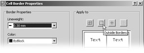
The Cell Borders shortcut menu option lets you modify the outline of the border. When you select this option, the Cell Border Properties dialog box appears.
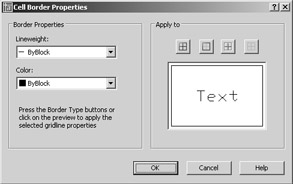
You can use this dialog to fine-tune the appearance of the line work of the table. Try the following exercise to see firsthand how this dialog box works:
-
Turn on the display of line weights by choosing Format Lineweight.
-
At the Lineweight Settings dialog box, turn on the Display Lineweight setting; then click OK.
-
Click in the title cell at the very top of the table to select the cell, and then right-click and select Cell Borders. The Cell Border Properties dialog box appears.
-
Click the Lineweight drop-down list and select 0.30 mm.
-
Click the Outside Borders button in the Apply To group to tell AutoCAD to change the borders of the cell to the selected line weight.
-
Click OK. The title cell is now outlined in a heavier line.
You can also adjust the line weights that encircle a group of cells, as in the following exercise:
-
Click in the cell in the upper-left corner with the Number label.
-
Shift+click the cell in the lower-right corner of the table so that all the cells from the second- from-the-top row down are selected.
-
Right-click and select Cell Borders.
-
Select 0.30 mm from the Lineweight drop-down list again. Then click the Outside Borders button again as you did in step 5 of the previous exercise.
-
Click OK. The outline of the selected cells are given the new line-weight setting.
Tip In addition to the table borders, you can change the background color for the cells of the table through the Background Fill option in the Properties palette. Select a group of cells in the table that you want to affect (but don't select the entire table), right-click, and select Properties. At the Properties palette, click the Background Fill option in the Cell group.
The Cell Border Properties dialog box also lets you set the line colors by selecting a color from the Color drop-down list before selecting an Apply To option.
In addition, the Apply To group offers four buttons : All Borders, Outside Borders (which you've already tried), Inside Borders, and No Borders. The All Borders options applies the changes to all borders. The Inside borders option applies the changes to just the inside borders. This option works only if you have selected multiple cells. The No borders option lets you clear your border selections if you change your mind.
If you want to select only the vertical or horizontal inside borders, you can use the graphic in the Cell Border Properties dialog box to select either the vertical or horizontal inside border. You can also use the graphic to select individual sides of the outside border by clicking on the sample border in the graphic. The sample will change to show you which border lines are affected.
Exporting Tables
You might someday want to export your AutoCAD table to a spreadsheet program or database. You can do this through a somewhat hidden option in a shortcut menu. Take the following steps:
-
Select the entire table. You can do so by clicking in a spot above and to the right of the table. With the crossing selection window, completely enclose the table and click.
-
Right-click anywhere in the table and select Export from the shortcut menu. The Export data dialog box appears. This is a typical file dialog box.
-
Specify a name and location for your exported table data and click Save.
Notice that the file is saved with a .csv filename extension. This type of file is a comma-delimited file and can be read by most spreadsheet programs including Microsoft Excel. Unfortunately, the.csv file does not retain the AutoCAD table formatting. To open the exported file from Excel, choose File Open in the Excel menu bar, and then at the Open dialog box, select Text File (*.prn, *.txt, *.csv). You can then locate the exported table and open it.
| Tip | You can also import spreadsheets and have them appear as AutoCAD tables. After they are imported, you can edit tables by using the same tools described in this chapter. Chapter 14 gives a detailed look at how to import a spreadsheet from Excel. |
| |
One of the more interesting features of the Table tool is its ability to include blocks in a cell. This can be useful if you want to include graphic elements in your table. Adding a block to a cell is a simple process. Here are the steps:
-
Click in a cell to select it.
-
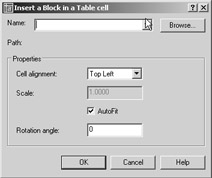
Right-click and select Insert Block from the shortcut menu. The Insert A Block In A Table Cell dialog box appears.
-
Select a block name from the Name drop-down list. You can also click the button to the right of the list to open a file dialog box that enables you to select a drawing file for import to the cell.
-
After you've selected a block and specified the settings in the Properties group of the dialog box, click OK. The block appears in the cell you've selected.
The Properties group in the dialog box enables you to specify the alignment and size of the inserted block. By default, the AutoFit option is turned on. This option adjusts the size of the block to make it fit in the current cell size.
| |
Creating Table Styles
If you find that you are creating the same table layout over and over, you can set up a set of predefined table styles. You can set up the properties of the title, column headings, and data in advance so you don't have to set them up each time you create a table. For example, if you prefer to use Arial bold at0.25 ² for the title and standard Arial at 0.125 ² for the column headings, you can create a table style with those settings. The next time you need to create a table, you can select your custom table style and specify the number of columns and rows; then you'll be ready to add the data without having to format the text.
To create a table style, take the following steps:
-
Choose Format Table Styles from the menu bar or enter TS
at the command prompt. The Table Style dialog box appears. You see the Standard table style in the list box. This is the one you used in the previous exercises. 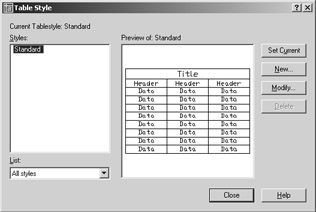
-
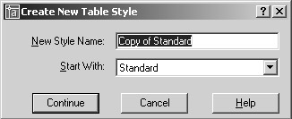
Click the New button. The Create New Table Style dialog box appears. This is where you give your new table style a name.
-
Enter My Table Style and click Continue. The New Table Style dialog box appears (see Figure 8.17).
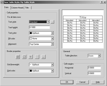
Figure 8.17: The New Table Style dialog box -
Click the Column Heads tab and then click the Title tab at the top of the dialog box. Notice that options for these tabs are nearly identical to those for the Data tab.
-
You'll learn more about the options in this dialog box next. For now, click OK to close the dialog box.
-
Notice that your new table style now appears in the Style list of the Table Style Dialog box. If you want to edit an existing table style, you can select the style from the list and click the Modify button. The Modify Table Style dialog box will appear, enabling you to edit the existing style. The Modify Table Style dialog box is identical to the New Table Style dialog box shown in Figure 8.17.
-
Click close to exit the dialog box.
After you've created a style, you can select it from the Table Style Settings group of the Insert Table dialog box that you used to create the sample table in Figure 8.16.
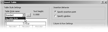
You can also get to the New Table Style dialog box by clicking the Table Style Dialog button just to the right of the Table Style Name drop-down list in the Insert Table dialog box.
The Table Style Options
Let's take a closer look at the New Table Style dialog box in Figure 8.17. You saw in step 4 of the previous exercise that each of the three tabs at the top of the dialog box contains the same set of options. This enables you to specify the text-formatting options for these three table elements: Data, Column Heads, and Title. You also have the option to turn off the column head row or the title row. As you make setting changes, the graphic to the right will show you how your changes affect your table style.
The dialog box includes these groups:
Cell Properties The Cell Properties group lets you format the text of the table. You can choose the text style, height, color, and alignment. A text style can be selected from the Text Style drop- down list, or you can click the button to the right of the drop-down list to open the Text Style dialog box. By offering this option, you can create a new text style if one doesn't exist to suit your needs. The Fill Color option lets you specify a background color for text cells.
Tip You can control the cell background color for existing tables by using the Properties palette. Click on a cell or group of cells, right-click, and select Properties. In the Properties palette, select a color from the Background Fill option.
Border Properties The Border Properties group lets you control the color and line weight of the table linework. The options in this group work just like the Cell Border Properties dialog box you saw in an earlier exercise.
General The General group has only one option. The Table Direction option lets you specify whether the table reads from top to bottom or from the bottom up.
Cell Margins Finally, the Cell Margins options let you specify the minimum distance between the text and the border of the cell. The Cell Margins options are useful when you find that the text is too close to one of the border lines.
Tip You can edit the table direction and cell margins of an existing table by using the Properties palette. Select the entire table and then right-click and select Properties from the shortcut menu. You'll find the Direction option and the Vertical and Horizontal cell margin options in the Table group of the Properties palette.
The Table tool is a powerful feature that has been on the wish list of many AutoCAD users. You've had the chance to see how it works with a small table in the previous exercise. Try experimenting with it to create some sample tables on your own. Or if you're anxious to learn how to import spreadsheets as tables, you can skip ahead to "Combining Data from Different Sources" in Chapter 14.
EAN: 2147483647
Pages: 261
- Structures, Processes and Relational Mechanisms for IT Governance
- An Emerging Strategy for E-Business IT Governance
- Linking the IT Balanced Scorecard to the Business Objectives at a Major Canadian Financial Group
- A View on Knowledge Management: Utilizing a Balanced Scorecard Methodology for Analyzing Knowledge Metrics
- The Evolution of IT Governance at NB Power