Specifying Distances with Coordinates
Next , you will continue with the Line command to draw a plan view (an overhead view) of a door, to no particular scale. Later, you will resize the drawing to use in future exercises. The door will be3.0 units long and 0.15 units thick. For metric users, the door will be 9 units long and 0.5 units thick. To specify these exact distances in AutoCAD, you can use either relative polar coordinates or Cartesian coordinates.
| |
Beginners and experts alike are bound to make a few mistakes. Before you get too far into the tutorial, here are some powerful yet easy-to-use tools to help you recover from accidents.
Backspace ( ) If you make a typing error, press the Backspace key to back up to your error, and then retype your command or response. The Backspace key is in the upper-right corner of the main keyboard area.
Escape (Esc) This is perhaps the single most important key on your keyboard. When you need to quickly exit a command or a dialog box without making changes, just press the Esc key in the upper-left corner of your keyboard. Before AutoCAD 2000, you had to press Esc twice in some instances. In more recent versions, you need to press Esc only once, though it won't hurt to press it twice. (Press Esc before editing with grips or issuing commands through the keyboard.)
U
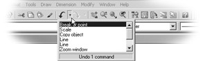
If you accidentally change something in the drawing and want to reverse that change, click the Undo tool in the Standard toolbar (the left-pointing curved arrow). You can also type U
Undo
You can open the Undo drop-down list by clicking the downward pointing arrow found to the right of the Undo tool.
Redo

| |
| Warning | The Imperial and metric distances are not equivalent in the exercises in this chapter. For example, 3 units in the Imperial-based drawing is not equal to 9 metric units. These distances are arbitrary and based on how they will appear in the figures in this chapter. |
Specifying Polar Coordinates
To enter the exact distance of 3 (or 9 metric) units to the right of the last point you selected, do the following:
-
Type @3<0 . Metric users should type @9<0 . As you type, the letters appear at the command prompt.
-
Press
. A line appears, starting from the first point you picked and ending 3 units to the right of it (see Figure 2.2). You have just entered a relative polar coordinate. 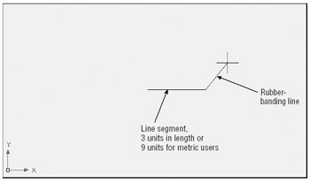
Figure 2.2: Notice that the rubber-banding line now starts from the last point selected. This indicates that you can continue to add more line segments.
The "at" sign (@) you entered tells AutoCAD that the distance you are specifying is from the last point you selected. The 3 (or 9 metric) is the distance, and the less-than symbol (<) tells Auto- CAD that you are designating the angle at which the line is to be drawn. The last part is the value for the angle, which in this case is 0. This is how to use polar coordinates to communicate distances and directions to AutoCAD.
| Tip | If you are accustomed to a different method for describing directions, you can set AutoCAD to use a vertical direction or downward direction as 0 °. See Chapter 3 for details. |
Angles are given based on the system shown in Figure 2.3, in which 0 ° is a horizontal direction from left to right, 90 ° is straight up, 180 ° is horizontal from right to left, and so on. You can specify degrees, minutes, and seconds of arc if you want to be that exact. I'll discuss angle formats in more detail in Chapter 3.
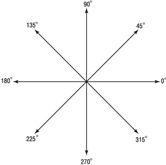
Figure 2.3: AutoCAD's default system for specifying angles
Specifying Relative Cartesian Coordinates
For the next line segment, let's try another method for specifying exact distances:
-
Enter @0,0.15
. Metric users should enter @0,0.5 . A short line appears above the endpoint of the last line. Once again, the @ tells AutoCAD that the distance you specify is from the last point picked. But, in this example, you give the distance in X and Y values. The X distance, 0, is given first, followed by a comma, and then the Y distance, 0.15. This is how to specify distances in relative Cartesian coordinates. Tip Step 1 indicates that metric users should enter @0,0.5
for the distance. Instead, you could enter 0,.5 (zero comma point five). The leading zero is included for clarity. European metric users should be aware that the comma is used as a separator between the X and Y components of the coordinate. In AutoCAD, commas are not used for decimal points; you must use a period to denote a decimal point. -
Enter @-3,0
. Metric users should enter @-9,0 . This distance is also in X,Y values, but here you use a negative value to specify the X distance. The result is a drawing that looks like Figure 2.4. 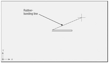
Figure 2.4: These three sides of the door were drawn by using the Line tool. Points are specified by using either relative Cartesian or polar coordinates.Positive values in the Cartesian coordinate system are from left to right and from bottom to top (see Figure 2.5). (You might remember this from your high school geometry class!) If you want to draw a line from right to left, you must designate a negative value. It is also helpful to know where the origin of the drawing lies. In a new drawing, the origin, or coordinate 0,0, is in the lower-left corner of the drawing.
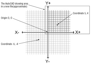
Figure 2.5: Positive and negative Cartesian coordinate directions -
Type C
. This C stands for the Close command. It closes a sequence of line segments. A line connecting the first and last points of a sequence of lines is drawn (see Figure 2.6), and the Line command terminates. The rubber-banding line also disappears, telling you that AutoCAD has finished drawing line segments. You can also use the rubber-banding line to indicate direction while simultaneously entering the distance through the keyboard. See the upcoming side- bar "A Fast Way to Enter Distances." 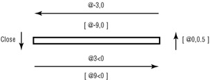
Figure 2.6: Distance and direction input for the door. Distances for metric users are shown in brackets.Tip To finish drawing a series of lines without closing them, you can press Esc,
, or the spacebar.
EAN: 2147483647
Pages: 261