Creating Complex Solids
As you learned earlier, you can convert a polyline into a solid by using the Extrude option on the Solids toolbar. This process lets you create more-complex shapes than the built-in primitives. In addition to the simple straight extrusion you've already tried, you can also extrude shapes into curved paths, or you can taper an extrusion .
Tapering an Extrusion
Let's look at how you can taper an extrusion to create a fairly complex solid with little effort:
-
Draw a 3 3 closed polyline at the top of the current solid. Start near the back-left corner of the bracket at coordinate 3.5,3,1, and then draw the 3 3 closed polyline to fit in the top of the composite solid, as shown in Figure 18.15.
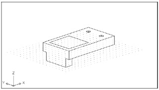
Figure 18.15: Drawing the 3 3 polyline boxWarning Remember to use the Close option to create the last side of the box.
-
Click the Fillet tool on the Modify toolbar. At the Select first object or [Polyline/Radius/Trim/mUltiple]: prompt, type R
 to set the radius of the fillet.
 -
At the prompt for the fillet radius, type 0.5
. -
Type P
to tell the Fillet command that you want to fillet a polyline. -
Click the polyline. The corners become rounded.

What Are Isolines? You might have noticed the message that reads as follows :
Current wire frame density: ISOLINES=4
This message tells you the current setting for the Isolines system variable, which controls the way curved objects, such as cylinders and holes, are displayed. A setting of 4 causes a cylinder to be represented by four lines with a circle at each end. You can see this in the holes that you've created for the Bracket model in the previous exercise. You can change the Isolines setting by entering Isoline
at the command prompt. You then enter a value for the number of lines to use to represent surfaces. This setting is also controlled by the Contour Lines Per Surface option in the Display tab of the Options dialog box. -
Click the Extrude button on the Solids toolbar or enter Ext
at the command prompt. -
At the Select objects: prompt, pick the polyline you just drew and press
. -
At the Specify height of extrusion or [ Path ]: prompt, enter 3
. -
At the Specify angle of taper for extrusion <0>: prompt, enter 4 for 4 ° of taper. The extruded polyline looks like Figure 18.16.
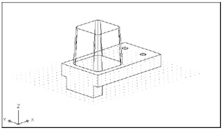
Figure 18.16: The extruded polyline -
Now join the part you just created with the original solid. Choose Modify Solid Editing Union, and then select the extruded part and the rectangular solid just below it. Press
to complete your selection. Tip In step 9, you can indicate a taper for the extrusion. Specify a taper in terms of degrees from the z-axis, or enter a negative value to taper the extrusion outward. Or press
to accept the default of 0 °, to extrude the polyline without a taper.
Extruding on a Curved Path
As you'll see in the following exercise, the Extrude command lets you extrude virtually any polyline shape along a path that is defined by a polyline, an arc, or a 3D polyline:
-
Choose View Zoom Extents and turn off the grid.
-
Choose View Hide. This helps you view and select parts of your model in the following steps.
-
Place the UCS on a vertical plane perpendicular to the back of the bracket. Choose Tools Orthographic UCS Left. The UCS orientation will appear as shown in the top image in Figure 18.17.
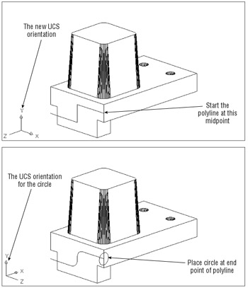
Figure 18.17: Hidden-line view showing how to set up your drawing to create a curved extrusion -
Start a polyline at the point shown in Figure 18.17. Use the Midpoint Osnap to make sure you select the midpoint of the vertical corner edge. After you locate the first point, enter the following coordinates:
@2<180
@1<270
@2<180When you are finished, your drawing should look like the first image in Figure 18.17.
-
Click the Fillet tool on the Modify toolbar, and then type R
to set the fillet radius. -
Enter 0.4
for the fillet radius. -
Type P
to select the Polyline option. -
Click the polyline you drew on the back side of the solid. The second image in Figure 18.17 shows the resulting filleted polyline.
-
Choose Tools New UCS Y and then enter 90
. This rotates the UCS 90 ° around the y-axis so the UCS is perpendicular to the front face of the solid. -
Draw a circle with a 0.35-unit radius at the location shown in the second image in Figure 18.17.
Tip
At this point, you've created the components needed to do the extrusion. Next , you'll finish the extruded shape:
-
Click the Extrude button on the Solids toolbar, click the circle, and then press
. -
At the Specify height of extrusion or [Path]: prompt, type P
to enter the Path option. -
At the Select extrusion path or [Taper angle]: prompt, click the polyline curve. Auto- CAD pauses a moment and then generates a solid "tube" that follows the path. The tube might not look like a tube because AutoCAD draws extruded solids such as this with four lines showing its profile.
-
Click the Subtract tool on the Solids Editing toolbar or choose Modify Solids Editing Subtract, and then select the rectangular solid.
-
Press
. At the Select objects: prompt, click the curved solid and press . The curved solid is subtracted from the square solid. Your drawing will look like Figure 18.18. 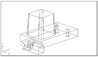
Figure 18.18: The solid after subtracting the curve
In this exercise, you used a curved polyline for the extrusion path, but you can use any type of 2D or 3D polyline, as well as lines and arcs, for an extrusion path.
Revolving a Polyline
When your goal is to draw a circular object, you can use the Revolve command on the Solids toolbar to let you create a solid that is revolved, or swept in a circular path. Think of Revolve's action as similar to a lathe that lets you carve a shape from a spinning shaft. In this case, the spinning shaft is a polyline, and rather than carving it, you define the profile and then revolve the profile around an axis.
In the following exercise, you will draw a solid that will form a slot in the tapered solid:
-
Zoom in to the top of the tapered box, so you have a view similar to Figure 18.19.
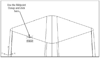
Figure 18.19: An enlarged view of the top of the tapered box and the new UCS location -
Turn off the Snap mode.
-
Return to the WCS by choosing Tools New UCS World.
-
Choose Tools New UCS Origin.
-
At the Specify new origin point <0,0,0>: prompt, use the Midpoint Osnap override and pick the midpoint of the top surface, as shown in Figure 18.19.
-
Set the Snap distance to 0.25 and turn on Polar Tracking.
-
Draw a polyline by using Polar Tracking with the following polar coordinates:
Start at -0.25,0 @.75<90
@.75<0
@.7071<315
@.5<0
@.7071<45
@.75<0
@.75<270 -
When you've finished, type C
to close the polyline. AutoCAD will not revolve an open polyline. Your drawing should look like Figure 18.20. 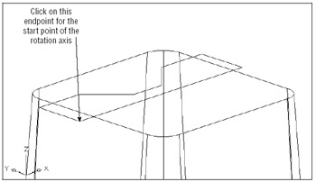
Figure 18.20: Drawing the polyline -
 Click the Revolve tool on the Solids toolbar or type Rev at the command prompt.
 -
At the Select objects: prompt, pick the polyline you just drew and press
. -
When you see the next prompt
Specify start point for axis of revolution or define axis by “[Object/X(axis)/Y(axis)]:
use the Endpoint Osnap override and pick the beginning endpoint of the polyline you just drew.
-
At the Specify endpoint of axis : prompt, turn on the Ortho mode (press F8) and turn off the Snap mode (press F9). Then pick a point to the far left of the screen so that the rubber- banding line is parallel with the x-axis of the current UCS.
-
At the Specify angle of revolution <360>: prompt, press
to sweep the polyline a full 360 °. The revolved form appears, as shown in Figure 18.21. 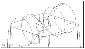
Figure 18.21: The revolved polyline
You just created a revolved solid that will be subtracted from the tapered box to form a slot in the bracket. But before you subtract it, you need to make a slight change in the orientation of the revolved solid:
-
Choose Modify 3D Operation Rotate 3D.
-
At the Select objects: prompt, select the revolved solid and press
. -
At the prompt
Specify first point on axis or define axis by [Object/Last/View/Xaxis/Yaxis/Zaxis/2points]:
use the Midpoint Osnap and click the right-side edge of the top surface, as shown in Figure 18.22.
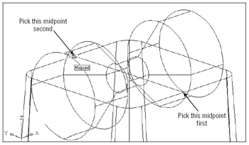
Figure 18.22: Selecting the points to rotate the revolved solid in 3D space -
At the Specify second point on axis: prompt, use the Midpoint Osnap again and click the opposite side of the top surface, as shown in Figure 18.22.
-
At the Specify rotation angle or [Reference]: prompt, type 5
. The solid rotates 5 °. -
Click the Subtract tool on the Solids Editing toolbar or choose Modify Solids Editing Subtract, click the tapered box, and then press
. -
At the Select objects: prompt, click the revolved solid and press
. Your drawing looks like Figure 18.23. 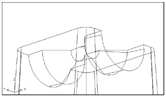
Figure 18.23: The composite solid
EAN: 2147483647
Pages: 261
- Integration Strategies and Tactics for Information Technology Governance
- Assessing Business-IT Alignment Maturity
- Linking the IT Balanced Scorecard to the Business Objectives at a Major Canadian Financial Group
- Measuring and Managing E-Business Initiatives Through the Balanced Scorecard
- A View on Knowledge Management: Utilizing a Balanced Scorecard Methodology for Analyzing Knowledge Metrics