Viewing Your Model in Perspective
ACAD only So far, your views of 3D drawings have been in parallel projection. This means that parallel lines appear parallel on your screen. Although this type of view is helpful while constructing your drawing, you will want to view your drawing in true perspective from time to time, to get a better feel for what your 3D model actually looks like.
AutoCAD provides the 3D Orbit tool to help you get the 3D view you want. You can use the 3D Orbit tool to refine your parallel projection views, but it is also the gateway to perspective views of your model. 3D Orbit has a lot of features and settings. With this in mind, you might want to begin these exercises when you know you have an hour or so to complete them all at one sitting.
| Tip | LT users do not have the 3D Orbit tool, but many of the functions of 3D Orbit are duplicated in the Dview command, which is available in LT. Consult the AutoCAD 2005 Instant Reference on the companion CD or the Auto- CAD LT help system for more information on the Dview command. |
If you are ready now, let's begin! Follow these steps to see a side view of the chair :
-
On the CD Open the Setting.dwg (or setting-metric.dwg ) file from the companion CD. You'll use this file to practice using the 3D Orbit tool. This file contains a simple 3D model of some chairs, a table, and a lamp.
-
Right-click any toolbar and then choose 3D Orbit from the shortcut menu. Open the View toolbar as well.
-
 Click the Camera tool on the View toolbar.
 -
At the Specify new camera position: prompt, click the lower-left corner of the drawing, as shown in Figure 16.36.
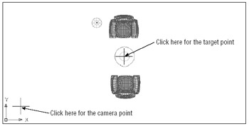
Figure 16.36: Selecting the camera and target points -
At the Specify new camera target: prompt, click the center of the circle that appears in the middle of the drawing, as shown in Figure 16.36. Your view changes to a side view of the chairs, as shown in Figure 16.37.
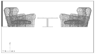
Figure 16.37: The side view of the chairs
This new view is from the camera point that you specified in step 4. The view's center is the target point you selected in step 5. Now you're ready to use the 3D Orbit tool. The camera and target points you selected are at the 0 coordinate on the z-axis, so your view is aimed at the bottom of the chairs. That's why the view is oriented toward the top of the screen.
In these steps, you'll use 3D Orbit to change your view:
-
 Click the 3D Orbit tool on the 3D Orbit toolbar. You can also choose View 3D Orbit. You see a circle with four smaller circles at its cardinal points. This circle is called an arcball. Along with the cursor, the archball helps you control your view. In addition, the UCS icon changes to appear shaded.
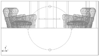
-
Place the cursor on the small circle at the top of the arcball. The cursor changes its appearance to a vertically elongated ellipse.
-
Click and drag the cursor downward from the top circle of the arcball, but don't let go yet. The view follows your cursor, and the motion is restrained to be vertical. When you have a view similar to Figure 16.38, release the mouse button.
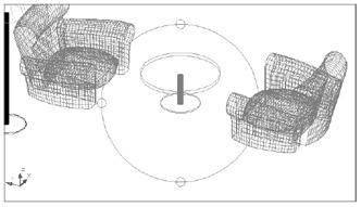
Figure 16.38: The view after clicking and dragging the top arcball circle
When you click and drag the circle at the top or bottom of the arcball, your view rotates about the target point you selected in step 5 of the first exercise in this section. You can relocate the rotation point by using the Camera tool to select a new target point.
Now let's continue by rotating the view sideways :
-
Place the cursor on the circle on the left side of the arcball. Notice that this time the cursor changes to look like an ellipse that is elongated horizontally.
-
Click and drag the cursor to the left from this circle on the arcball, but don't let go. The view now rotates about the target point from left to right.
-
Position your view so it looks like Figure 16.39 and release the mouse.
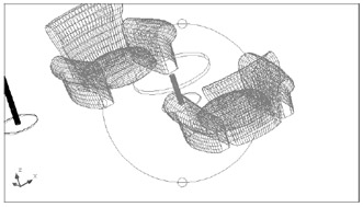
Figure 16.39: The view after clicking and dragging the left arcball circle
By now, you should have a feel for the way the arcball works. You click and drag until you get the view you want. But right now, the view is not exactly right. You'll want to rotate the view to straighten it out:
-
Move the cursor to the outside of the arcball. Notice that it now looks like a circle.
-
With the cursor outside the arcball, click and drag downward. The view rotates in the direction that you move the cursor.
-
Adjust the view until it looks similar to the one in Figure 16.40.
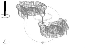
Figure 16.40: The view straightened out
When the cursor appears as a circle, you can rotate the view in the view plane. This enables you to "straighten" your view after you've moved your viewpoint or camera location.
You've tried nearly all the arcball options. There's one more option that is a combination of the top and side circles. Try these steps:
-
Place the cursor inside the arcball. The cursor now looks like two superimposed ellipses.
-
Click and drag the cursor and move it in a slight circular motion. Notice how the view pivots in all directions about the target point.
-
Return the view to the one shown in Figure 16.40.
This last option gives you a bit more freedom to move the view, though it can be a bit unwieldy.
| Tip | You can change the target point, and therefore the point around which your 3D Orbit view rotates, by using the Camera tool on the View toolbar. Click the Camera tool; then press |
Turning On a Perspective View
The view is still a bit high in the AutoCAD window. You will want to move it downward to include more of the lamp and the chair at the top. You're also still viewing your drawing in a parallel projection mode.
In this exercise, you'll switch to a Perspective view and then use the Pan tool to center your view:
-
Right-click and choose Projection Perspective from the shortcut menu. Your view changes to a perspective one. The view is a bit high, so you'll want to use the 3D Orbit Pan tool to center your view.
-
 Right-click and choose Pan from the shortcut menu. You can also select 3D Pan from the 3D Orbit toolbar. The arcball disappears, and the cursor turns into the familiar Pan cursor.
 -
Click and drag the view downward to center the table top in the view. Your view should look like Figure 16.41.
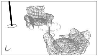
Figure 16.41: The Perspective view after panning downward
You saw several things happen in this brief exercise. First, you saw how easy it is to obtain a Perspective view. You were also introduced to the 3D Orbit shortcut menu. This menu offers a few options that don't appear on the 3D Orbit toolbar.
You also used the Pan tool on the 3D Orbit toolbar. This tool works just like the standard Pan tool you've been using all along, but there is a difference. You might have noticed that when you panned your view, the perspective changed as you panned. The effect is similar to that of looking out a car's side window as you move down the highway . When you pan your view by using the 3D Pan tool on the 3D Orbit toolbar, you are moving both the camera viewpoint and the target point together. This maintains your camera and target orientation while moving the overall scene.
Using Some Visual Aids
You're still in 3D Orbit mode, even though you no longer see the arcball. This can be a bit confusing. You can use a visual aid to remind yourself that 3D Orbit is still active:
-
Right-click and then choose Visual Aids Compass from the shortcut menu. The 3D Orbit Compass appears.
-
Right-click again and choose Visual Aids Grid. A grid appears at the zero Z coordinate.
-
To help visualize the forms of the objects in this scene, turn on the Shade mode. Right-click and then choose Shading Modes Hidden. You've already seen both the Grid and the Hidden Shade mode in Chapter 15. Figure 16.42 shows how your view will look after turning on the Compass, Grid, and Hidden Shade modes.
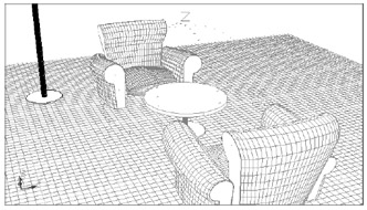
Figure 16.42: The view with the Compass, Grid, and Hidden Shade modes turned on
You might have noticed that the options under the Shading Modes cascading menu were the same options available from the Shade toolbar. They're offered in the 3D Orbit menu for easy access, in case you want to view your model with hidden lines removed.
EAN: 2147483647
Pages: 261