Creating a Polyline Spline Curve
The Pedit command's Spline option (named after the spline tool used in manual drafting) offers you a way to draw smoother and more controllable curves than those produced by the Fit option. A poly- line spline does not pass through the vertex points as a fitted curve does. Instead, the vertex points act as weights pulling the curve in their direction. The polyline spline touches only its beginning and end vertices. Figure 13.16 illustrates this concept.
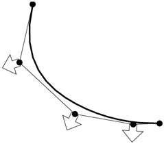
Figure 13.16: The polyline spline curve pulled toward its vertices
| Tip | A polyline spline curve does not represent a mathematically true curve. See the next section, "Using True Spline Curves," to learn how to draw a more accurate spline curve. |
Let's see how using a polyline spline curve might influence the way you edit a curve:
-
Undo the width changes you made in the previous exercise.
-
To change the contour into a polyline spline curve, choose Modify Object Polyline.
-
Pick the polyline to be curved .
-
At the prompt
Enter an option [Close/Join/Width/Edit vertex/Fit/Spline/Decurve/Ltype gen/Undo]:
 enter S
 . Your curve changes to look like Figure 13.17.
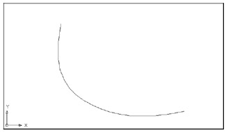
Figure 13.17: A spline curve -
Press
to exit Edit Polyline.
The curve takes on a smoother, more graceful appearance. It no longer passes through the points you used to define it. To see where the points went and to find out how spline curves act, do the following:
-
Make sure the Noun/Verb Selection mode and the Grips feature are turned on.
-
Click the curve. You'll see the original vertices appear as grips (see the first image in Figure 13.18).
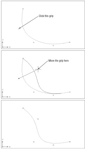
Figure 13.18: The fitted curve changed to a spline curve, with the location of the second vertex and the new curve -
Click the grip that is second from the top of the curve, as shown in the second image in Figure 13.18, and move the grip around. Notice how the curve follows , giving you immediate feedback on how the curve will look.
-
Pick a point as shown in the third image in Figure 13.18. The curve is fixed in its new position.
Tip You can set up AutoCAD to display both the curved and the straight segments defining the curve by turning on the Splframe system variable. Enter splframe
1 and then issue a Regen command. You'll see a frame that connects the grips of the curve. To turn off the display of the straight segments, enter splframe .
EAN: 2147483647
Pages: 261