The Importance of QoS on 802.11 Networks
|
|
When the suggestion is made that 802.11 and the associated protocols could potentially replace the PSTN, one of the first considerations is to provide an alternative to the primary service for which the PSTN was built—voice. A great deal of attention to detail is required to engineer a data network that carries voice. The primary objection to VoIP, the primary means of transmitting voice over a packet network, is that the QoS of an IP network is inadequate to deliver intelligible voice to the subscriber. The limitations of an IP network to deliver adequate QoS for voice and video include latency, jitter, and packet loss. By delivering adequate QoS for voice service, 802.11 presents an alternative to the PSTN's voice services. By delivering good QoS for video delivery, the 802.11 network provides an alternative to a cable or satellite TV service.
In order to best define QoS, this chapter addresses QoS on wired IP networks before describing how many of those concepts apply to wireless networks. IP is the same regardless of whether it is transmitted via a wired or wireless means of transmission. Latency is the chief detractor from QoS in both instances. QoS concerns do not end at the AP. An alternative IP-based network must address QoS end to end.
QoS in Wired IP Networks
A chief objection to VoIP is the notion that the QoS of the VoIP product is inferior to the PSTN. A similar comparison would be made between 802.11 and cable or satellite in the delivery of video services. QoS covers a number of parameters, but is mostly concerned with the users' perception of the voice quality as well as the call setup and keeping the call up for the intended duration of the call (avoiding dropped calls).
Volumes have been written on QoS on IP networks. This chapter sets forth measures that improve QoS on an IP network that makes QoS, especially voice quality over an IP network, as good as that of the PSTN. 802.11 can also offer QoS for video services to compete with cable and satellite services. Earlier in the history of the industry, the perception was that IP voice quality was not as good as that of circuit-switched voice. International Telecommunication Union—Telecommunication Standardization Sector (ITU-T) Recommendation E.800 defines QoS as "The collective effect of service performance, which determines the degree of satisfaction of a user of the service." Service providers often state that the QoS end-user experience must equal the PSTN end-user experience. With proper engineering, a VoIP network can deliver QoS that is just as good or better than that of the PSTN.
Factors Affecting QoS in Wired IP Networks
The four most important network parameters for the effective transport of VoIP traffic over an IP network are bandwidth, delay, jitter, echo, and packet loss. Voice and video quality is a highly subjective thing to measure. This presents a challenge for network designers who must first focus on these issues in order to deliver the best QoS possible. This chapter explores the solutions available to service providers that will deliver the best QoS possible. Table 5-3 describes some factors affecting VoIP voice quality.
| Factor | Description |
|---|---|
| Delay | Latency between transmitting an IP packet to receiving the packet at destination. |
| Jitter | Variation in arrival times between continuous packets transmitted from point A to point B. Caused by packet routing changes, congestion, and processing delays. |
| Bandwidth | Greater bandwidth delivers better voice quality. |
| Packet loss | The percentage of packets never received at the destination. |
It is necessary to scrutinize the network for any element that might induce delay, jitter, packet loss, or echo. This includes the hardware elements such as routers and media gateways, and routing protocols that prioritize voice packets over all other types of traffic on the IP network.
Improving QoS in IP Routers and the Gateway
End-to-end delay is the time required for a signal generated at the caller's mouth to reach the listener's ear. Delay is the impairment that receives the most attention in the media gateway industry. It can be corrected via functions contained in the IP network routers, the VoIP gateway, and engineering in the IP network. The shorter the end-to-end delay, the better the perceived quality and overall user experience. The following sections discuss sources of delay.
Sources of Delay—IP Routers Packet delay is primarily determined by the buffering, queuing and switching, or routing delay of the IP routers. Packet capture delay is the time required to receive the entire packet before processing and forwarding it through the router. This delay is determined by the packet length, link layer operating parameters, and transmission speed. Using short packets over high-speed trunks can easily shorten the delay. VoIP networks use packetization rates to balance connection bandwidth efficiency and packet delay.
Switching or routing delay is the time it takes a network element to forward a packet. New IP switches can significantly speed up the routing process by making routing decisions and forwarding the traffic in hardware devices instead of software. Due to the statistical multiplexing nature of IP networks and the asynchronous nature of packet arrivals, some delay in queuing is required at input and output ports of a packet switch. Overprovisioning router and link capacities can reduce this delay in queuing time.
Sources of Delay—VoIP Gateways If a voice conversation, for example, has to cross between analog and IP networks, the conversation will have to transit a VoIP gateway. This transition may induce delay in the transmission and degrade the QoS of the conversation. Voice signal processing at the sending and receiving ends, which includes the time required to encode or decode the voice signal from analog or digital form into the voice-coding scheme selected for the call and vice versa, adds to the delay. Compressing the voice signal also increases the delay. The greater the compression, the greater the delay of the packet stream. If bandwidth costs are not a concern, a service provider can utilize G.711, which is uncompressed voice, which imposes a minimum of delay due to the lack of compression.
On the transmit side, packetization delay is another factor that must be entered into the calculations. The packetization delay is the time it takes to fill a packet with data. The larger the packet size, the more time is required. Using shorter packet sizes can shorten this delay, but will increase the overhead because more packets have to be sent, all containing similar information in the header. Balancing voice quality, packetization delay, and bandwidth utilization efficiency is very important to the service provider.[9]
How much delay is too much? Of all the factors discussed in Chapter 4, "Security and 802.11," which outlined the factors that degrade VoIP, latency (or delay) is the greatest. Recent testing by Mier Labs offers a metric for VoIP voice quality. That measure is to determine how much latency is acceptable comparable to the voice quality offered by the PSTN. Latency less than 100 milliseconds (ms) does not affect toll-quality voice. However, latency over 120 ms is discernable to most callers, and at 150 ms, the voice quality is noticeably impaired, resulting in less than toll-quality communication. The challenge for VoIP service providers and their vendors is to get the latency of any conversation on their network to not exceed 100 ms.[10] Humans are intolerant of speech delays of more than about 200 ms. As mentioned earlier, ITU-T G.114 specifies that delay is not to exceed 150 ms one way or 300 ms round trip. The dilemma is that although elastic applications (e-mail, for example) can tolerate a fair amount of delay, they usually try to consume every bit of network capacity they can. In contrast, voice applications need only small amounts of the network, but that amount has to be available immediately.[11] Figure 5-5 illustrates delay across a network, including delay in a gateway.
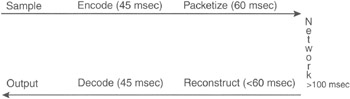
Figure 5-5: Delay across a network including delay in a gateway (coding and packetizing)
Other Gateway Improvements Gateways can be engineered to minimize impairments to QoS. Those impairments are echo, end-to-end delay, buffering delay, and silence suppression. Echo is a phenomenon where a transmitted voice signal is reflected back due to an unavoidable impedance mismatch and a four-wire/two-wire conversion between the telephone handset and the communication network. Echo can disrupt the normal flow of conversation and its severity depends on the round-trip time delay. If a round-trip time delay is more than 30 ms, the echo becomes significant, making normal conversation difficult. A gateway should have an echo canceller so that when delay reaches above 30 ms, the echo canceller circuits can control the echo.
Occasionally, some cells might arrive late due to a delay in transit. In order to ensure that no under-runs occur, the buffer size should exceed the maximum predicted delay. The size of the buffer translates into delay, as each packet must progress through the buffer at the receiving gateway at the emulated circuit's line rate.
Voice communication is half duplex, which means that one person is silent while the other speaks. A gateway can save bandwidth by halting the transmission of cells at the gateway during these silent periods. This is known as silence suppression, or voice activation detection (VAD). Gateways can also offer comfort noise generation, which approximates the buzz found on the PSTN and lets the user duplicate the PSTN experience with which he or she is most comfortable. Many gateways offer these functions.[12]
Recent research performed by the Institute for Telecommunications Sciences in Boulder, Colorado, compared the voice quality of traffic routed through VoIP gateways with the PSTN. Researchers were fed a variety of voice samples and were asked to determine if the sample originated from the PSTN or the VoIP gateway traffic. The result of the test was that the voice quality of the VoIP gateway-routed traffic was "indistinguishable from the PSTN."[13] It should be noted that the IP network used in this test was a closed network and not the public Internet or other long-distance IP network. This report indicates that quality media gateways can deliver QoS on the same level as the PSTN. The challenge then shifts to ensuring the IP network can deliver similar QoS.
Improving QoS in the Network
QoS requires the cooperation of all logical layers in the IP network—from application to physical media—and of all network elements from end to end. Clearly, optimizing QoS performance for all traffic types on an IP network presents a daunting challenge. To partially address this challenge, several Internet Engineering Task Force (IETF) groups have been working on standardized approaches for IP-based QoS technologies. The IETF's approaches fall into the following categories:
-
Prioritization using the Resource Reservation Protocol (RSVP) and differentiated services (DiffServ)
-
Label switching using Multiprotocol Label Switching (MPLS)
-
Bandwidth management using the subnet bandwidth manager
To greatly simplify the objection that VoIP voice quality is not equal to the PSTN, the problem is overcome by engineering the network to diminish delay and jitter by instituting RSVP, DiffServ, and/or MPLS on the network. The International Softswitch Consortium in its reference architecture recommends RSVP, DiffServ, and MPLS as mechanisms to ensure QoS for VoIP networks.
Resource Reservation (RSVP) A key focus in this industry is to design IP networks that will prioritize voice packets. One of the earlier initiatives is integrated services (IntServ), which was developed by the IETF. It is characterized by the reservation of network resources prior to the transmission of any data. RSVP, which is defined in RFC 2205, is the signaling protocol that is used to reserve bandwidth on a specific transmission path. RSVP is designed to operate with routing protocols such as Open Shortest Path First (OSPF) and the Border Gateway Protocol (BGP). The IntServ model is comprised of a signaling protocol (RSVP), an admission control routine (determines network resource availability), a classifier (puts packets in specific queues), and a packet scheduler (schedules packets to meet QoS requirements). The latest development is a control/signaling protocol called the Resource Reservation Protocol—Traffic Engineering (RSVP-TE). It can be used to establish a traffic-engineered path through the router network for high-priority traffic. This traffic-engineered path can operate independent of other traffic classes.
The IEEE initiative 802.1p is a specification that provides a method to allow preferential queuing and access to media resources by traffic class on the basis of a priority value signaled in the frame. This value provides a consistent method for Ethernet, token ring, or other Media Access Control (MAC) layer media types across the subnetwork. The priority field is defined as a 3-bit value, resulting in a range of values between 0 and 7, with 0 assigned as the lowest priority and 7 indicating the highest priority. Packets may then be queued based on their relative priority values.[14]
RSVP currently offers two levels of service. The first level is guaranteed, which comes as close as possible to circuit emulation. The second level is controlled load, which is equivalent to the service that would be provided in a best-effort network under no-load conditions. Table 5-4 covers reservation, allocation and policing.
| Reservation, Allocation, and Policing | |
|---|---|
| RSVP | RSVP provides reservation setup and control to enable the resource reservation that integrated services prescribe. Hoses and routers use RSVP to deliver QoS requests to routers along data stream paths and to maintain router and host state to provide the requested service—usually bandwidth and latency. |
| Real-Time Protocol (RTP) | RTP offers another way to prioritize voice traffic. Voice packets usually rely on the User Datagram Protocol (UDP) with RTP headers. RTP treats a range of UDP ports with strict priority. |
| Committed Access Rate (CAR) | CAR, a traffic-policing mechanism, allocates bandwidth commitments and limitations to traffic sources and destinations while specifying policies for handling traffic that exceeds the bandwidth allocation. Either the network's ingress or application flows can apply CAR thresholds. |
| Source: IEEE | |
RSVP works where a sender first issues a PATH message to the far end via a number of routers. The PATH message contains a traffic specification (Tspec) that provides details about the data packet size. Each RSVP-enabled router along the way establishes a path state that includes the previous source address of the PATH message. The receiver of the PATH message responds with a Reservation Request (RESV) that includes a flow specification (flowspec). The flowspec includes a Tspec and information about the type of reservation service requested, such as controlled-load service or guaranteed service.
The RESV message travels back to the sender along the same route that the PATH message took (in reverse). At each router, the requested resources are allocated, assuming that they are available and that the receiver has the authority to make the request. Finally, the RESV message reaches the sender with a confirmation that resources have been reserved.[15]
Guaranteed service (as opposed to controlled load, see RFC 2212) involves two elements. The first ensures that no packet loss occurs. The second ensures minimal delay. Ensuring against packet loss is a function of the token bucket depth (b) and the token rate (r) specified in the Tspec. At a given router, provided that buffer space of value b is allocated to a given flow and that a bandwidth of r or greater is assigned, there should be little to no loss. Hence, uncompressed voice usually delivers better QoS than compressed voice.
Delay is a function of two components. The first is fixed delay due to the processing within the individual nodes and is only a function of the path taken. The second component of delay is the queuing delay within the various nodes. Queuing is an IP-based QoS mechanism that is available in conventional packet forwarding systems and can differentiate and appropriately handle isochronous traffic. Numerous mechanisms have been designed to make queuing as efficient as possible. Table 5-5 describes these mechanisms.
| Queuing | Description |
|---|---|
| First in, first out (FIFO) | FIFO, also known as the best-effort service class, simply forwards packets in the order of their arrival. |
| Priority queuing (PQ) | PQ allows prioritization on some defined criteria called a policy. Four queues—high, medium, normal, and low—are filled with arriving packets according to the policies defined. DiffServ code point (DSCP) packet marking can be used to prioritize such traffic. |
| Custom queuing (CQ) | CQ permits the allocation of a specific amount of a queue to each class while leaving the rest of the queue to be filled in round-robin fashion. It essentially facilitates the prioritization of multiple classes in queuing. |
| Weighted fair queuing (WFQ) | WFQ schedules interactive traffic to the front of the queue to reduce response time, and then fairly shares the remaining bandwidth among high-bandwidth flows. |
| Class-based weighted fair queuing (CBWFQ) | CBWFQ combines CQ and WFQ. This strategy gives higher weight to higher-priority traffic, defined in classes using WFQ processing. |
| Low-latency queuing (LLQ) | LLQ brings strict PQ to CBWFQ. It gives delay-sensitive data (voice) preferential treatment over other traffic. This mechanism forwards delay-sensitive packets ahead of packets in other queues. |
Controlled-load service (see RFC 2211) is a close approximation of the QoS that an application would receive if the data were being transmitted over a network that was lightly loaded. A high percentage of packets will be delivered successfully and the delay experienced by a high percentage of the packets will not exceed the minimum delay experienced by any successfully delivered packet.
Differentiated Service (DiffServ) Another IETF initiative is DiffServ (see RFC 2474). DiffServ sorts packets that require different network services into different classes. Packets are classified at the network ingress node according to SLAs. DiffServ is a set of technologies proposed by the IETF to enable Internet and other IP-based network service providers to offer differentiated levels of service to individual customers and their information streams. On the basis of a DSCP marker in the header of each IP packet, the network routers would apply differentiated grades of service (GoSs) to various packet streams, forwarding them according to different per-hop behaviors (PHBs). The preferential GoS, which can only be attempted and not guaranteed, includes a lower level of packet latency as those packets advance to the head of a packet queue if the network suffers congestion.[16]
DiffServ makes use of the IP version 4 Type of Service (ToS) field and the equivalent IP version 6 Traffic Class field. The portion of the ToS/Traffic Class field that DiffServ uses is known as the DS field. The field is used in specific ways to mark a given stream as requiring a particular type of forwarding. The type of forwarding to be applied is PHB. DiffServ defines two types of PHB: expedited forwarding (EF) and assured forwarding (AF).
PHB is the treatment that a DiffServ router applies to a packet with a given DSCP value. A router deals with multiple flows from many sources to many destinations. Many of the flows can have packets marked with a DSCP value that indicates a certain PHB. The set of flows from one node to the next that share the same DSCP is known as an aggregate. From a DiffServ perspective, a router operates on packets that belong to specific aggregates. When a router is configured to support a given PHB, the configuration is established in accordance with aggregates rather than to specific flows from a specific source to a specific destination.
EF (RFC 2598) is a service in which a given traffic stream is assigned a minimum departure rate from a given node—that is, one that is greater than the arrival rate at the same node. The arrival rate must not exceed a prearranged maximum. This process ensures that queuing delays are removed. As queuing delays are the chief cause of end-to-end delay and jitter, this process ensures that delay and jitter are minimized. The objective is to provide low loss, low delay, and low latency such that the service is similar to a virtual leased line. EF can provide a service that is equivalent to a virtual leased line.
The EF PHB can be implemented in a network node in a number of ways. Such a mechanism could enable the unlimited preemption of other traffic such that EF traffic always receives access to outgoing bandwidth first. This could lead to unacceptably low performance for non-EF traffic through a token bucket limiter. Another way to implement the EF PHB would be through the use of a weighted round-robin scheduler, where the share of the output bandwidth allocated to EF traffic is equal to a configured rate.
AF (RFC 2597) is a service in which packets from a given source are forwarded with a high probability, assuming the traffic from the source does not exceed a prearranged maximum. If it does exceed that maximum, the source of the traffic runs the risk that the data will be lumped in with normal best-effort IP traffic and will be subject to the same delay and loss possibilities. In a DiffServ network, certain resources will be allocated to certain behavior aggregates, which means that a smaller share is allocated to standard best-effort traffic. Receiving best-effort service in a DiffServ network could be worse than receiving best-effort service in a non-DiffServ network. A given subscriber to a DiffServ network might want the latitude to occasionally exceed the requirements of a given traffic profile without being too harshly penalized. The AF PHB offers this possibility.
The AF PHB enables a provider to offer different levels of forwarding assurances for packets received from a customer. The AF PHB enables packets to be marked with different AF classes and different drop-precedence values within each class. Within a router, resources are allocated according to the different AF classes. If the resources allocated to a given class become congested, then packets must be dropped. Packets that have higher drop-precedence values will be dropped. The objective is to provide a service that ensures that high-priority packets are forwarded with a greater degree of reliability than low-priority packets.
AF defines four classes, which are each allocated a certain amount of resources (buffer space and bandwidth) within a router. Within each class, a given packet can have one of three drop rates. At a given router, if congestion occurs within the resources allocated to a given AF class, the packets with the highest drop rate will be discarded first so that packets with a lower drop rate value will receive some protection. In order to function properly, the incoming traffic must not have packets with a high percentage of low drop rates. After all, the purpose is to ensure that the highest-priority packets get through in the case of congestion. That cannot happen if all the packets have the highest priority.[17]
In a DiffServ network, the AF implementation must detect and respond to long-term congestion by dropping packets and then respond to short-term congestion, which derives a smoothed long-term congestion level. When the smoothed congestion level is below a particular threshold, no packets should be dropped. If the smoothed congestion level is between a first and second threshold level, then packets with the highest drop-precedence level should be dropped. As the congestion level rises, more of the high drop-precedence packets should be dropped until a second congestion threshold is reached. At that point, all of the high drop-precedence packets are dropped. If the congestion continues to rise, then packets of the medium drop-precedence level should also start being dropped.
The implementation must treat all packets within a given class and precedence level equally. If 50 percent of packets in a given class and precedence value are to be dropped, then that 50 percent should be spread evenly across all packets for that class and precedence. Different AF classes are treated independently and are given independent resources. When packets are dropped, they are dropped for a given class and drop-precedence level. The packets of one class and precedence level might experience a 50 percent drop rate, whereas the packets of a different class with the same precedence level might not be dropped at all. Regardless of the amount of packets that need to be dropped, a DiffServ node must not reorder AF packets within a given AF class, regardless of their precedence level.[18]
MPLS-Enabled IP Networks MPLS has emerged as the preferred technology for providing QoS, traffic engineering, and virtual private network (VPN) capabilities on the Internet. MPLS contains forwarding information for IP packets that is separate from the content of the IP header such that a single forwarding paradigm (label swapping) operates in conjunction with multiple routing paradigms. The basic operation of MPLS is to establish label-switched paths (LSPs) through the network into which certain types of traffic are directed. MPLS provides the flexibility to form Forwarding Equivalence Classes (FECs) and the ability to create a forwarding hierarchy via label stacking. All of these techniques facilitate the operation of QoS, traffic engineering, and VPNs. MPLS is similar to DiffServ in that it marks traffic at the entrance to the network. The function of the marking is to determine the next router in the path from source to destination.
MPLS involves the attachment of a short label to a packet in front of the IP header. This procedure is similar to inserting a new layer between the IP layer and the underlying link layer of the Open Systems Interconnection (OSI) model. The label contains all of the information that a router needs to forward a packet. The value of a label can be used to look up the next hop in the path and forward it to the next router. The difference between this routing and standard IP routing is that the match is exact. This enables faster routing decisions in routers.[19]
An MPLS-enabled network, on the other hand, can provide low-latency and guaranteed traffic paths for voice. Using MPLS, voice traffic can be allocated to an FEC that provides the appropriate DiffServ for this traffic type. Significant work has been done recently to extend MPLS as the common control plane for optical networks.[20]
QoS in softswitched networks is corrected with mechanisms similar to those in time-division multiplexing (TDM) networks. By engineering out deficiencies in the components (media gateways) and improving the network (DiffServ and MPLS), QoS can be brought up to the standards of the PSTN. Although it not as quantifiable as a Mean Opinion Score (MOS) on a media gateway, significant progress has been made in recent years in engineering closed IP networks to deliver PSTN-quality voice.
MPLS is not primarily a QoS solution. MPLS is a new switching architecture. Standard IP switching requires every router to analyze the IP header and make a determination of the next hop based on the content of that header. The primary driver in determining the next hop is the destination address in the IP header. A comparison of the destination address with entries in a routing table and the longest match between the destination address and the addresses in the routing table determine the next hop. The approach with MPLS is to attach a label to the packet. The content of the table is specified according to an FEC, which is determined at the point of ingress to the network. The packet and label are passed to the next node, where the label is examined and the FEC is determined. This label is then used as a simple lookup in a table that specifies the next hop and new label to use. The new label is attached and the packet is forwarded.
The major difference between label switching and standard routing based on IP is that the FEC is determined at the point of ingress to the network where information might be available that cannot be indicated in the IP header. The FEC can be chosen based on a combination of the destination address, QoS requirements, the ingress router, or a variety of other criteria. The FEC can indicate information and routing decisions in the network automatically and take that information into account. A given FEC can force a packet to take a particular route through the network without having to cram a list of specific routers into the IP header. This is important for ensuring QoS where the bandwidth that is available on a given path has a direct impact on the perceived quality.[21]
MPLS Architecture MPLS involves the determination of an FEC value to apply to a packet at the point of the ingress to the network. That FEC value is then mapped to a particular label value and the packet is forwarded with the label. At the next router, the label is evaluated and a corresponding FEC is determined. A lookup is then performed to determine the next hop and new label to apply. The new label is attached and the packet is forwarded to the next node. This process indicates that the value of the label can change as the packet moves through the network.
Label-Switching Routers (LSRs) The relationship between the FEC and the label value is a local affair between two adjacent label-switching routers (LSRs). If a given router is upstream from the point of view of data flow, then it must have an understanding with the next router downstream as to the binding between a particular label value and FEC.
An LSR's actions depend on the value of the label. The LSR's action is specified by the Next Hop-Level Forwarding Entry (NHLFE), which indicates the next hop, the operation to perform on the label stack, and the encoding to be used for the stack on the outgoing link. The operation to perform on the stack might mean that the LSR should replace the label at the top of the stack with a new label. The operation might require the LSR to pop the label stack or replace the top label with a new label and then add one or more additional labels on top of the first label.
The next hop for a given labeled packet might be the same LSR. In such a case, the LSR pops the top-level label of the stack and forwards the packet to itself. At this point, the packet might still have a label to be examined, or it might be a native IP packet without a label (in which case, the packet is forwarded according to standard IP routing).
A given label might possibly map to more than one NHLFE. This might occur where load sharing takes place across multiple paths. Here, the LSR chooses one NHLFE according to internal procedures. If a router knows that it is the next-to-last LSR in a given path, it removes labels and passes the packet to the final LSR without a label. This is done to streamline the work of the last router. If the next-to-last LSR passes a labeled packet to the final LSR, then the final LSR must examine the label, determine that the next hop is itself, pop the stack, and forward the packet to itself. The LSR must then reexamine the packet to determine what to do with it. If the packet arrives without a label, then the final LSR has one less step to execute. The way a particular LSR determines that it is the next-to-last LSR for a given path is a function of label distribution and the distribution protocol used.[22]
Label-Switched Paths (LSPs) MPLS networks are subsets of a larger IP network. This means points of ingress and egress to the MPLS networks from the larger IP network will exist. An LSR that is a point of ingress to the MPLS network will be responsible for choosing the FEC that should be applied to a given packet. As label distribution works in a downstream-to-upstream direction, an LSR that is a point of egress is responsible for determining a label/FEC binding and passing that information upstream. An LSR will act as an egress LSR with respect to a particular FEC if the FEC refers to the LSR itself, if the next hop for the FEC is outside the label-switching network, or if the next hop involves traversing a boundary. An LSP is the path to a certain FEC from a point of ingress to the egress LSR. The primary function of label-distribution protocols (LDPs) is the establishment and maintenance of these LSPs.
Label-Distribution Protocol (LDP) In the MPLS architecture, the downstream LSR decides on the particular binding. The downstream LSR then communicates the binding to the upstream LSR, which means that an LDP must exit between the two to support such communication. Label distribution is performed in two ways. First, a downstream on demand exists, where a given LSR can request a particular label/FEC binding from a downstream LSR. Second, an unsolicited downstream is available, where a given LSR distributes label/FEC bindings to other upstream LSRs without having been explicitly requested to do so.
MPLS Traffic Engineering Performance objectives for VoIP networks are either traffic oriented or performance oriented. Traffic-oriented objectives deal with QoS and aim to decrease the impacts of delay, jitter, and packet loss. Performance-oriented objectives seek to make optimum usage of network resources, specifically network bandwidth. Congestion avoidance is a major objective related to both network resource objectives and QoS objectives. In regards to resource objectives, it is imperative to avoid having one part of a network congested while another part of the network is underutilized, where the underutilized part of the network could carry traffic from the congested part of the network. From a QoS perspective, it is necessary to allocate traffic streams where resources are available to ensure those streams do not experience congestion with resultant packet loss and delay.
Congestion occurs two ways. First, the network does not have adequate resources to handle the offered load. Second, the steering of traffic toward resources is already loaded as other resources remain underutilized. The expansion of flow control can correct the first situation. Good traffic engineering can overcome the limitations of steering traffic to avoid congestion. Current IP routing and resource allocation is not well equipped to deal with traffic engineering.
MPLS offers the concept of the traffic trunk, which is a set of flows that share specific attributes. These attributes include the ingress and egress LSRs, the FEC, and other characteristics such as the average rate, peak rate, and priority and policing attributes. A traffic trunk can be routed over a given LSP. The LSP that a traffic trunk would use can be specified. This enables certain traffic to be steered away from the shortest path, which is likely to be congested before other paths. The LSP that a given traffic trunk will use can be changed. This enables the network to adapt to changing load conditions either via administrative intervention or through automated processes within the network.
Traffic engineering on an MPLS network has the main elements of mapping packets to FECs, mapping FECs to traffic trunks, and mapping traffic trunks to the physical network topology through LSPs. The assignment of individual packets to a given FEC and how those FECs are further assigned to traffic trunks are functions specified at the ingress to the network. These decisions can be made according to various criteria, provided they are understood by both the MPLS network provider and the source of packets (customer or other network provider).
A third mapping that must take place revolves around providing the quality that is needed for a given type of traffic. This mapping involves constraint-based routing, where traffic is matched with network resources according to the characteristics of the traffic and characteristics of available resources. That is, one characteristic of traffic is the bandwidth requirement and one characteristic of a path is the maximum bandwidth that it offers.
To date, MPLS is considered the best means of engineering an IP network to handle voice traffic to deliver the best possible QoS. As this technology becomes more widely deployed in IP networks, VoIP will be delivered with a quality that is at least equal to the PSTN.[23]
[9]Bill Douskalis, IP Telephony: The Integration of Robust VoIP Services, (Upper Saddle River, NJ: Prentice Hall, 2000), 230–231.
[10]Mier Communications, "Lab Report — QoS Solutions," www.sitaranetworks.com/solutions/pdfs/mier_report.pdf, February 2001.
[11]John McCullough and Daniel Walker, "Interested in VoIP? How to Proceed," Business Communications Review (April 1999): 16–22.
[12]"Accelerating the Deployment of Voice over IP (VoIP) and Voice over ATM (VoATM)," a white paper from Telica as posted by International Engineering Consortium (IEC), www.iec.org.
[13]Andrew Craig, "Qualms of Quality Dog Growth of IP Telephony," Network News (November 11, 1999): 3.
[14]Anjali Agarwal, "Quality of Service (QoS) in the New Public Network Architecture," IEEE Canadian Review (Fall 2000): 1.
[15]Daniel Collins, Carrier Grade Voice over IP, (New York: McGraw-Hill, 2002), 362–363.
[16]Anjali Agarwal, "Quality of Service (QoS) in the New Public Network Architecture," IEEE Canadian Review (Fall 2000): 1.
[17]Collins, 384.
[18]Collins, 386–387.
[19]Collins, 384.
[20]"The Evolution Toward Multiservice IP/MPLS Networks," a white paper from Integral Access, www.integralaccess.com.
[21]Collins, 399.
[22]Collins, 399.
[23]Collins, 399.
|
|
EAN: 2147483647
Pages: 96
- Cell-Mode MPLS over ATM Overview, Configuration, and Verification
- Constraint-Based Routing and Operation in MPLS TE
- Configuring L2TPv3 Dynamic Tunnels
- VPLS Overview
- Case Study 2: Implementing Multi-VRF CE, VRF Selection Using Source IP Address, VRF Selection Using Policy-Based Routing, NAT and HSRP Support in MPLS VPN, and Multicast VPN Support over Multi-VRF CE