Interference
|
|
To most people, QoS in a wireless network refers to interference from other transmission sources. An immediate concern is a profusion of wireless appliances in day-to-day use such as garage door openers, microwave ovens, and cordless phones. The truth is many of these household appliances do not operate on the same frequency as 802.11 or the power of their emission is too low or distant to interfere with 802.11 traffic.
A wide variety of other devices (such as bar code scanners, industrial lighting and industrial heaters, and home microwave ovens) also use the same frequencies. As these local area networks (LANs) (and other devices in the Industrial, Scientific, and Medical [ISM] band) operate at fairly low power levels, the actual risk of interference is relatively slight, but it does exist. As the popularity of such LANs increases, situations have developed in which such interference has, indeed, become an issue.[1]
External Sources of Interference
Interference can be categorized as having two sources: external and internal. External sources are not related to the 802.11 network and are often categorized as garage door openers, some cordless phones, baby monitors, and so on. Internal sources originate in the 802.11 network. Table 5-1 summarizes the potential external sources of interference in 802.11 networks and their solutions.
| Source of Interference | Discounting Factor or Solution |
|---|---|
| Garage door opener | It is on the wrong frequency. |
| Microwave oven | Commercial microwaves may have the power to generate enough interference to interfere with a WLAN; residential microwaves do not have the power to generate enough interference to be a factor beyond the subscriber's premises. |
| Cordless phone | Cordless phones are considered to be a nonissue in the industry. They have too little power to interfere beyond the immediate residence or office. If a subscriber's cordless phone is interfering with his or her service, then the subscriber should replace the 2.4 GHz phone with a 900 MHz cordless phone. Why would a residence with a cell phone and voice over IP (VoIP) 802.11 service still use a PSTN-connected cordless phone? |
Debunking External Interference Myths Garage door openers are purported to provide interference to 802.11 LANs. This is a myth. Garage door openers operate in the 286 to 390 MHz band; therefore, they don't interfere with 802.11. Many cordless phones operate (900 MHz) in the 802 to 829 MHz ISM band and don't interfere with 802.11 either. However, 2.4 GHz cordless phones do operate on the same band as 802.11 and can cause interference. So how do you deal with interference from other applications of the 2.4 and 5.8 GHz bands since FCC Part 15 users are granted use on a noninterference basis?
The FCC licenses 802.11 wireless APs to operate under Class B, §15.247 of the FCC regulations in the 2.4 GHz ISM band. The regulations state that any device licensed to operate under Part 15 may not interfere with or otherwise disrupt the operation of licensed devices coexisting in the same spectrum. In other words, unlicensed Part 15 devices are the lowest priority. They come after the federal government's FCC-licensed services; Part 18 devices (ISM transmit-only devices) such as telemetry, radiolocation, and radio frequency (RF) heating and lighting; and Part 97 Amateur Radio Service. Also, other unlicensed Part 15 devices under the wrong conditions cause interference, such as 2.4 GHz cordless phones, Bluetooth applications, microwave ovens, and 2.4 GHz baby monitors.
Engineering Wireless LANs (WLANs) to Minimize External Interference To minimize external sources of interference, network planners must control the following five parameters:
-
The channel/band used
-
The distance to the interference (further is better)/the distance to intended signal (closer is better)
-
Power levels of interference (lower is better)
-
Antenna beam widths
-
The protocol used
Changing Channels Sometimes the easiest approach is to change the channel to an unused or lower congested channel. The specifications for both 802.11a and 802.11 stipulate multiple channels or frequencies. If interference is being encountered on one frequency, then it is merely a matter of switching frequencies to a channel that is not being interfered with. 802.11 provides 11 overlapping channels (for North America), which are 22 MHz wide and centered at 5 MHz intervals (beginning at 2.412 GHz and ending at 2.462 GHz). This means that only 3 channels do not overlap (channels 1, 6, and 11). Table 5-2 lists the 11 channels of 802.11 and their frequencies.
| Channel | Frequency (GHz) |
|---|---|
| 1 | 2.412 |
| 2 | 2.417 |
| 3 | 2.422 |
| 4 | 2.427 |
| 5 | 2.432 |
| 6 | 2.437 |
| 7 | 2.442 |
| 8 | 2.447 |
| 9 | 2.452 |
| 10 | 2.457 |
| 11 | 2.462 |
802.11a provides 12 channels, which are each 20 MHz wide and centered at 20 MHz intervals (beginning at 5.180 GHz and ending at 5.320 GHz for the lower and middle Unlicensed National Information Infrastructure [U-NII] bands, and beginning at 5.745 GHz and ending at 5.805 GHz for the upper U-NII band). It is important to note that none of these channels overlap.[2]
The 5 GHz U-NII band is far less congested, and Wi-Fi has a greater amount of spectrum in which to operate. It also permits more channels. The standards bodies are working on protocols that enable multiple APs to negotiate among themselves automatically for the proper frequency allocation. The 802.11g standard uses orthogonal frequency division multiplexing (OFDM) on 2.4 GHz, which is less susceptible to interference and provides more channels. However, the operational range of both 802.11g and 802.11a may be an issue in larger environments.[3]
Once a source of interference has been identified, a common practice among wireless Internet service providers (WISPs) is to negotiate and decide which broadcasters (the WISPs) will transmit on what frequency. If such an arrangement cannot be achieved, an WISP can switch to multiple channels in order to avoid interference.
Dealing with Distance A signal on the same frequency as the 802.11 WLAN, for example, will not cause interference if the source is too distant. That is, the interfering signal becomes too weak to present interference. In addition, if the distance between the AP and the subscriber device is greater than optimal, the signal becomes weak over the distance and becomes susceptible to interference as the interfering signal is greater than the desired signal.
If 802.11 is used as a last-mile solution providing access to a residence or small business, the potential sources of interference must be considered. If the sources of interference (cordless phones or microwave ovens) can be eliminated within the residence or small enterprise, then the second possible source of interference would come from neighboring residences. The potential for those sources of interference are limited by the distance to the subscriber's network and the power level of that interference. Household appliances such as microwave ovens and cordless phones generate too little power to offer interference beyond the building in which they are located unless the device is defective. For example, the door seal may need to be replaced. In this case, the defective microwave oven is a hazard in itself.
Engineering with Power The power levels of the primary and interfering signals must also be taken into account. If the power level of the interfering signal gets close to the power level of the intended 802.11 or other WLAN signal, then interference will occur. The simplest solution is to increase the power level of the WLAN signal in order to overcome the interfering signal. The limitation here is that the service provider must not interfere with licensed spectrum operators on similar (unlikely) spectrum. The other solution is to reduce the power level of the interfering signal. However, it is important to understand that increasing the power can cause interference for other users of the band and that FCC regulations set legal power output limits.[4]
Antenna Beam Widths Another way to eliminate interference is to use antennas to shape where the transmitter's signal goes and where the receiver listens. A narrow beam width antenna can increase the effective power toward the receiver and also increase the signal strength of the received signal.
Steerable Antennas Another engineering approach to overcome QoS issues is to use smart antenna technology. Steering the antenna can do the following for the wireless network: Improve the signal-to-noise ratio (SNR) with beam forming, reduce interference due to channel reuse, and mitigate intersymbol interference in multipath environments. Much of this technology falls under the heading of multiple in, multiple out (MIMO).
San Francisco-based Vivato is now marketing their Wi-Fi, the first of their kind. Wi-Fi switches deliver the power of network switching with phased-array radio antennas. These Wi-Fi switches use phased-array radio antennas to create highly directed, narrow beams of Wi-Fi transmissions. The Wi-Fi beams are created on a packet-by-packet basis. Vivato calls this technology PacketSteering™.
Unlike current WLAN broadcasting, Vivato's switched beam is focused in a controlled pattern and pointed precisely at the desired client device. These narrow beams of Wi-Fi enable simultaneous Wi-Fi transmissions to many devices in different directions, thus providing parallel operations to many users-the essence of Wi-Fi switching. These narrow beams also reduce co-channel interference, since they are powered only when needed.[5]
Protocol By using 802.11g instead of 802.11, you gain the advantage of OFDM, which is less susceptible to interference and multipath.
Other Approaches Other approaches can be taken to control interference. The environment can be controlled so that the interference is limited by controlling the devices used. For example, many airports are requiring all RF applications to be run through their frequency coordinators. The correct band can be chosen for each application. A WISP may consider using 802.11a so that its wireless wide area network (WWAN) does not interfere with a possible WLAN solution.
Internal Sources of Interference
Thus far, this chapter has focused on sources of interference that are external to the wireless network. As mentioned in the introduction, a number of challenges arise within a wireless network due to the nature of wireless transmissions. These sources of interference include multipath and channel noise. Both can be engineered out of the network.
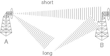
Figure 5-2: Signal interference on 802.11 wireless networks
Multipath and Fade Margin Multipath occurs when waves emitted by the transmitter travel along a different path and interfere destructively with waves traveling on a direct line-of-sight path. This is sometimes referred to as signal fading. This phenomenon occurs because waves traveling along different paths may be completely out of phase when they reach the antenna, thereby canceling each other. Because signal cancellation is almost never complete, one method of overcoming this problem is to transmit more power. In an indoor environment, multipath is almost always present and tends to be dynamic (constantly varying). Severe fading due to multipath can result in a signal reduction of more than 30 dB. It is therefore essential to provide an adequate link margin to overcome this loss when designing a wireless system. Failure to do so will adversely affect reliability. The amount of extra RF power radiated to overcome this phenomenon is referred to as fade margin or system operating margin. The exact amount of fade margin required depends on the desired reliability of the link, but 802.11 protocols usually have a 15 to 20 dB fade margin, ensuring a 95 percent confidence interval.[6]
One method of mitigating the effects of multipath is ensuring antenna diversity. Since the cancellation of radio waves is geometry dependent, using two (or more) antennas separated by at least half of a wavelength can drastically mitigate this problem. Upon acquiring a signal, the receiver checks each antenna and simply selects the antenna with the best signal quality. This reduces, but does not eliminate, the required link margin that would otherwise be needed for a system that does not employ diversity. The downside is that this approach requires more antennas and a more complicated receiver design. Another method of dealing with the multipath problem is via the use of an adaptive channel equalizer. Adaptive equalization can be used with or without antenna diversity.
After the signal is received and digitized, it is fed through a series of adaptive delay stages that are summed together via feedback loops. This technique is particularly effective in slowly changing environments such as transmission over telephone lines, but it is more difficult to implement in rapidly changing environments like factory floors, offices, and homes where transmitters and receivers are moving in relation to each other. The main drawback is the impact on system cost and complexity. Adaptive equalizers can be expensive to implement for broadband data links.
Spread spectrum systems are fairly robust in the presence of multipath. Direct sequence spread spectrum (DSSS) systems reject reflected signals that are significantly delayed relative to the direct path or strongest signal. This is the same property that enables multiple users to share the same bandwidth in Code Division Multiple Access (CDMA) systems. However, 802.11's DSSS does not have enough processing gain and orthogonal spreading codes to do this. Frequency-hopping spread systems (FHSS) also exhibit some degree of immunity to multipath. Because an FHSS transmitter is continuously changing frequencies, it always hops to frequencies that experience little or no multipath loss. In a severe fading environment, the throughput of an FHSS system will be reduced, but it is unlikely that the link will be lost completely. OFDM systems such as 802.11a and 802.11g transmit on multiple subcarriers on different frequencies at the same time. Multipath is limited in much the same way in that it is limited in an FHSS system. Also, OFDM specifies a slower symbol rate to reduce the chance a signal will encroach on the following signal, minimizing multipath interference.
Channel Noise When evaluating a wireless link, three important questions should be answered:
-
How much RF power is available?
-
How much bandwidth is available?
-
What is the required reliability (as defined by the bit error rate [BER])?
In general, RF power and bandwidth effectively place an upper bound on the capacity of a communications link. The upper limit in terms of data rate is given by Shannon's Channel Capacity Theorem, as shown in Equation 5-1:
| (5-1) |
where:
-
C = channel capacity (bits per second)
-
B = channel bandwidth (hertz)
-
S = signal strength (watts)
-
N = noise power (watts)
Note that this equation means that for an ideal system, the BER will approach zero if the data transmission rate is below the channel capacity. In the real world, the degree to which a practical system can approach this limit is dependent on the modulation technique and receiver noise.
For all communications systems, channel noise is intimately tied to bandwidth. All objects that have heat emit RF energy in the form of random (Gaussian) noise. The amount of radiation emitted can be calculated by Equation 5-2:
| (5-2) |
where:
-
N = noise power (watts)
-
k = Boltzman's constant (1.38×10⁻²³ J/K)
-
T = system temperature (K), usually assumed to be 290K
-
B = channel bandwidth (hertz), predetection
This is the lowest possible noise level for a system with a given physical temperature. For most applications, temperature is typically assumed to be room temperature (290K). Equations 5-1 and 5-2 demonstrate that RF power and bandwidth can be traded off to achieve a given performance level (as defined by BER).[7] This implies that using a lower data rate that occupies a lower channel bandwidth will provide better range.
If You Want Interference, Call the Black Ravens
One of the co-author's first real jobs was that of the Intelligence Office, Tactical Electronic Warfare Squadron 135 (abbreviated VAQ-135 with the nickname "World-Famous Black Ravens") of the U.S. Navy. This squadron flew EA-6B tactical jamming aircraft (see Figure 5-3). The airplane is equipped with an ALQ-99 jamming system and is used to jam enemy radar and radio communications in a tactical role. It has been rumored for many years that the squadron's four aircraft, strategically positioned, could shut down most of the electromagnetic spectrum of the United States (TV, radio, and so on).
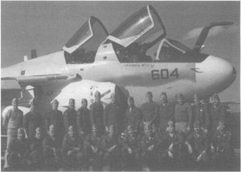
Figure 5-3: EA-6B tactical jamming aircraft of the U.S. Navy-the "World-Famous Black Ravens." Coauthor Franklin Ohrtman is the first person on the left, standing.
In a strategic role during the Cold War, the U.S. Air Force developed the B-52G, which was a bomber equipped with an extensive suite of electronic jamming equipment designed to defeat the Soviet air defenses. This would require overwhelming air defense overlapping radar networks that operated at a variety of frequencies. It would also deliver overwhelming interference on air defense radio communications, making the airwaves unusable for the Soviets. By shutting down Soviet air defense radars and negating their ability to communicate by radio, the B-52G would clear a path for itself and other strategic bombers to targets for destruction by nuclear attack. A trivia question on student exams at the U.S. Navy's Electronic Warfare School in the 1980s asked, "What is the electromagnetic coverage of the B-52G jamming system?" The correct answer was "DC (Direct Current) to daylight."
Given the potential for interference at tactical and strategic military applications relative to the electromagnetic spectrum, it is trivial to negate the benefits of wireless networks based on perceived interference from garage door openers, home microwave ovens, or cordless phones. With proper network engineering, interference from household appliances can be negated.
[1]Ray Horak, "Wireless LANs (WLANs): Focus on 802.11," www.commweb.com/article/COM20020827S0003.
[2]"A Comparison of 802.11a and 802.11 Wireless LAN Standards," a white paper from Linksys, www.linksys.com/products/images/wp_802.asp.
[3]Chris Fine, "Watch out for Wi-Fi," a report from Goldman Sachs, September 26, 2002, 35.
[4]See FCC Regulations, Part 15.247 and 15.407, www.fcc.gov.
[5]"Vivato Switches Are Changing the Physics of Wireless," a white paper from Vivato, www.vivato.net/prod_tech_technology.html.
[6]Jim Zyren and Al Petrick, "Tutorial on Basic Link Budget Analysis," a white paper from Intersil, www.intersil.com/data/an/an9804.pdf.
[7]Jim Zyren and Al Petrick, "Tutorial on Basic Link Budget Analysis," a white paper from Intersil, www.intersil.com/data/an/an9804.pdf.
|
|
EAN: 2147483647
Pages: 96