IRQs and IO Ports
IRQs and I/O PortsAlthough many new network adapter cards support plug-and-play capabilities, which means the operating system can automatically detect and configure them, this capability is not implemented in all operating systems, such as many Unix variants. Because of this, you might find yourself having to configure a card manually when upgrading a system with a new card, or when adding other devices that might conflict with the NIC. The two main items you will commonly have to modify are the values for the IRQ and the base I/O port. IRQsWhen a device on the computer's bus needs to get the attention of the CPU, it uses a hardware mechanism called the Interrupt Request Line ( IRQ ). Hardware interrupts are executed by signaling the CPU through a set of wires that are connected to the pins that attach the CPU to the motherboard. It is a direct connection. Because various devices might need to get the CPU's attention at any particular time, one IRQ is not sufficient. Instead, in most cases each device has its own interrupt line. When a device signals the CPU using an interrupt, it is telling the CPU that it has a processing request that needs to be satisfied as quickly as possible. When the CPU receives an interrupt, it grants the device its attention for a short period ”as long as it is not currently servicing another interrupt of a higher priority. It is also possible that the CPU is performing some task that is too critical to allow for an interrupt. When that is the case, the CPU does not allow a hardware interrupt to distract it. For that reason, this type of interrupt is called a maskable interrupt . This means that the CPU can be put into a mode in which it masks out these interrupts while it is busy on an ultra -important task, and then re-enables the interrupts when it is again capable of processing them. The number of IRQs that are available on the system depends on the system bus type. Early PCs that were based on the ISA bus type had only eight hardware interrupts, numbered from 0 to 7, as shown in Table 7.1. Table 7.1. ISA Bus Hardware Interrupts
This small set of IRQs was sufficient for a small system with few devices. As you can see, only one IRQ ”2 ”is available for an additional device in this layout. When the EISA bus was developed, the number of interrupts doubled to 16 (numbered 0 through 15). However, to do this, two interrupt controllers were needed on the system; one of them funnels its interrupts through IRQ2. This means that there are actually only 15 interrupts available for use by other devices on the system. Table 7.2 shows the devices that usually use these IRQs. Table 7.2. EISA Bus Hardware Interrupts
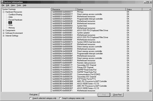
Notice that the IRQ numbers in Table 7.2 are not in numerical order. Instead, they are listed in order of priority , with those at the top of the table having a higher priority than those at the bottom. Because the additional eight IRQs were added by a mechanism that uses the original IRQ2, those IRQs all have a higher priority than IRQs 3 “7. On some systems, IRQ9 is used to perform the same functions that were done by IRQ2 in the earlier design. For this reason, you might see this IRQ on a card labeled as 2, 9, or possibly IRQ 2/9. If your computer is a plug-and-play system, you might find that you do not need to make any changes to the card or the system software to select the IRQ. If you do, however, be sure to consult the documentation that comes with the card to determine which interrupts it can use and how they are set. IRQs in non “plug-and-play cards are usually set by jumpers on the card, but sometimes through a software configuration utility. A jumper consists of a set of pins that can be connected to form a complete circuit by placing a connector between them. Base I/O PortsAgain, if you find yourself in a situation in which your computer's operating system does not provide plug-and-play capabilities, you might have to manually configure the value of the memory address that the network card uses to transfer data to and from the system. After the network card signals to the CPU that processing needs to be done, it uses a memory address called the base I/O port address for this purpose. Because many devices in the system might use memory port addresses, it is important to configure each device to use a different address so that any data transfers that are performed do not conflict with each other. On most systems, 64KB of memory is set up to be used for I/O ports, so they do not represent a limited resource like the IRQ does. Consult your operating-system documentation to determine how to display the current memory assignments for this area of memory. For example, in Microsoft Windows 2000/2003, a utility called Microsoft Diagnostics can be used to display various hardware and software configurations. In Figure 7.5 you can see the utility, displaying the I/O ports on a Windows 2003 Server computer. Note the other selections on the left side of the MMC window. You can check IRQs, memory usage, and other things when trying to diagnose problems with network cards and other devices. Figure 7.5. The Windows 2003 Diagnostics utility can show you how I/O ports are assigned. To run the diagnostic utility on a Windows 2000/2003 Server system, select Start, Programs (All Programs for Windows 2003 systems), Accessories, System Tools, System Information. When the utility appears, select the Hardware Resources tab. Click the I/O Port selection on the left side of the MMC and your screen should look similar to that shown in Figure 7.5. Notice that the first item listed is Conflicts/Sharing. Using this item, you can determine whether more than one device on this system is sharing an interrupt. In addition to the base I/O port, some devices use a section of memory to buffer data temporarily. For this, they require a base memory address , which points to the start of the buffer. Your network card might or might not use the computer's RAM, so check the documentation carefully if a conflict arises. |
EAN: 2147483647
Pages: 434