LAN Topologies
| Several unique network technologies have been developed over the past three decades. Different types of networks have different design criteria and, thus, various topologies have come into use. One important distinction needs to be made before we enter into a serious discussion on topology: physical topology versus logical topology. The physical topology describes the layout of a network media (such as copper and fiber-optic cables and, more recently, wireless equipment) and the devices that connect to it. The logical topology is concerned not with the actual physical connections but with the logical path through the network that data can take from one place to another. The differences will be more evident as the different topologies are discussed. The basic topologies you will find in most LANs today include the following:
Bus TopologyThe simple bus topology structure was the first type used in Ethernet networks. The typical bus physical topology consists of a coaxial cabling common to all computer systems connected to the LAN. This coax is tapped in multiple places along its length, with each tap being used as a point of connection for a computing system. Taps can be physical cores cut into the coax (sometimes called a "vampire tap") or BNC-style "T-connectors" that join several individual pieces of coax together to form the common bus (see Figure 2.1 and Figure 2.2 for a comparison of the two methods). Figure 2.1. Computers can connect to coaxial cables on a bus by tapping directly through the core of the cable. The vampire taps pierce the thicknet cable but not the BNC. Figure 2.2. BNC-style T-connectors make attaching computers to a bus a simpler operation.
A bus is also a logical topology. From a device's viewpoint, all other systems communicate through the same, shared path. Because it is a shared media technology, mechanisms must be put into place to arbitrate network traffic over the cable. Typically, collision detection (CD) or collision avoidance (CA) algorithms are used in bus topologies to arbitrate network access along with concepts such as "broadcasts" to reach every device on the cable. This subject is covered in detail in Chapter 13. The bus topology is very simple and inexpensive to implement due to its low cost requirements for cable installation (there's only one main trunk). But some serious deficiencies make bus topology LANs unattractive to deploy:
Due to these limitations, the bus topology is typically found only in the smallest or most austere of installations. Some proprietary manufacturing process control systems use a bus topology, but these aren't covered in this book. For the most part, the bus topology is a historical relic. However, it is something you should be cognizant of in order to understand why other topologies are the norm today. Early networks were composed of only a few computers and there was no need to provide for today's high-bandwidth networks that use switches and other devices to connect a diverse collection of computers and other networked devices. Star TopologyThe concept behind the star topology is simple. Every node on the LAN has a dedicated cable that is pulled back to a centralized point, typically a wiring closet. All cables are terminated in a network component within the closet, such as a hub or, more typically today, a switch, which handles the repeating or switching of traffic out to the other nodes on the network (see Figure 2.3). Figure 2.3. The star topology enables you to centralize wiring for a network. The shortcomings of a star topology network are obvious: The network switch (or hub) is a single point of failure, and a great deal of wiring is involved to implement the star. However, there are tremendous benefits to a star topology that outweigh most of its inefficiencies:
You should note that nearly every popular network technology today uses a star topology for its physical implementation. This is due to several factors, including the ease of wiring (there's just a lot of it), the fact that a single misbehaving computer can be removed from the topology, and the fact that it's a simple matter to set up a hub or switch. Note When troubleshooting a star topology network, be sure to check error counters and status indicators on your network components. These can provide valuable information in helping you find what is at fault. If you use wireless Ethernet (Wi-Fi) for part or all of your network, note that the infrastructure for a wireless network also uses a star topology but with these differences:
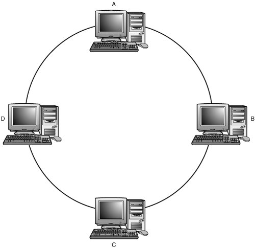
Some WAPs also include an Ethernet switch, so you can also have a star topology that mixes wired and wireless clients. Ring TopologyRing topologies are more complex than the bus and star topologies discussed in previous sections, but they offer some attractive features. Nodes logically communicate in a ring formation, with each node communicating only directly with its upstream and downstream neighbors (see Figure 2.4). Figure 2.4. The ring topology links each node on the network to two other nodes on the network. You can probably picture what a mess the wiring would be in an office with hundreds of computer systems, if a network like this were implemented as a physical ring. So ring topologies are typically implemented in a physical star topology (see Figure 2.5). Figure 2.5. The ring topology is usually implemented as a physical star to simplify wiring management. In a ring topology, access to the network is controlled through a token that is passed from node to node as the arbitration mechanism. Each node takes its turn at claiming the token as the token passes from neighbor to neighbor, and when a node possesses the token, it takes its turn to transmit onto the ring. A data packet is transferred from one node to the next until it reaches its destination node. After the destination node has received the packet, it modifies the packet to acknowledge receipt and passes it on. Eventually, the packet makes it completely around the ring, and the transmitting node receives it and notes that the receipt has been acknowledged. When the transmitting node is finished, it releases the token to its neighbor, and the process repeats. Note Token-Ring networks are the primary LAN technology that uses a ring topology. Although Token-Ring technology today represents only a small percentage of network installations, another network, the Storage Area Network (SAN) still uses the concept of a ring topology, with a different method for gaining access to the network media than the method used by Token-Ring networks. In Chapter 11, "Network Attached Storage and Storage Area Networks," you will find that Arbitrated Loops continue to use the ring topology to provide access to storage devices, such as disk and tape drives, to high-end servers. The Arbitrated Loop maintains a ring topology but uses an arbitration priority method based on device addresses to gain access to the loop instead of the token-passing mechanism used by Token-Ring networks. Newer SANs are built using a switched network technology often referred to as a SAN fabric. As you will read in Chapter 11, it is possible to attach an Arbitrated Loop to a SAN fabric to preserve your current investment. The benefits of this kind of topology can be readily observed:
Another ring topology called Fiber Distributed Data Interface (FDDI) uses dual fault-tolerant rings. This technology requires that the two rings have tokens passing in opposite directions of one another. A breakdown in one ring causes the nodes to shift over to the secondary ring to continue communications. The down side of a ring topology is simple: The firmware required to manage the ring is somewhat complicated and must be on every network card that participates in the ring. Because Ethernet dominates the marketplace today, you can purchase an inexpensive 100Mbps Ethernet network adapter for less than $20, and a Gigabit Ethernet adapter for less than $50. Token-Ring network adapters are more difficult to find, and they tend to be much more expensive devices than their Ethernet counterparts ($150 or more per network adapter). As a result, technologies such as Ethernet have transitioned rapidly to higher networking speeds while ring topologies have never quite jumped the speed gap. The ring topologies that exist today have changed little in the past 10 to 15 years. Note In Chapter 12, "The IEEE LAN/MAN Committee Networking Standards," you will see that development on Token-Ring networks has pretty much come to an end-of-life state as far as standards are concerned. Although Token-Ring networks are still used in some vertical market applications (such as the factory floor), Ethernet technology has become the norm for the LAN. If you want to learn more about Token-Ring networks, you can visit the primary vendors of this technology at www.networking.ibm.com/ and at www.madge.com. Mesh TopologyA mesh topology is an interlacing of multiple connections among several nodes. Typically, a mesh is done for one purpose: redundancy. Any serious campus network must incorporate a mesh to achieve the level of redundancy and fault tolerance that businesses demand from their data networks. There are two types of mesh: full and partial. Except in the smallest network, a full mesh is not very practical, but it is mentioned here for completeness. Full mesh means that every node contained in a network has a connection to every other node contained in the network. It should be fairly obvious at this point why full meshes are not very practical (see Figure 2.6). The cost for such infrastructure would be exorbitant, and 90% of it would never be put to use. Figure 2.6. A full mesh topology is not a very practical way to wire a network. Partial meshes are designed to provide redundancy where it is needed. By using a little forethought in design, a network architect could place some additional connectivity where it can provide needed bandwidth and fault tolerance to the network. Suppose for a moment that an important resource were attached to node A, as shown in Figure 2.7. Figure 2.7. A partial mesh topology can be used to provide redundancy for the network. You can spot several paths that could fail, yet all the nodes of your network would still be able to reach node A as a destination. The true merits of partial mesh are realized when you look at WAN and campus topologies. Mesh topologies are used on a small scale by ad-hoc wireless networks. In an ad-hoc network, there is no WAP. Instead, each station communicates with other stations. Ad-hoc wireless networks work well for tasks such as folder or printer sharing or for distributing streaming media, but an ad-hoc wireless network cannot connect with another network or with the Internet unless one computer with a direct Internet connection is using Internet Connection Sharing (ICS) to share its connection with other computers on the network. Note that the computer with the shared connection acts as a gateway for other computers, and if it is shut down or otherwise loses its connection to the Internet, all other computers lose their connection as well. Hybrid TopologiesHubs or switches can be attached to one another to create larger LANs capable of supporting more devices. After this happens, you start getting some interesting hybrid topologies. Three popular hybrids are tree, hierarchical star, and star-wireless. TreeFigure 2.8 shows a combination topology that groups workstations in a star and joins the stars along a linear bus. The majority of the problems of the bus are eliminated because a single workstation cannot bring the entire LAN to a halt. You still can add or change workstations by plugging them into a different port on the same hub, or on another hub. If one hub malfunctions, it disables only the workstations that are attached to it from communicating on the network. The remaining workstations on the other hubs can continue to function normally. Figure 2.8. A combination of the bus and star topologies groups workstations in a star and joins them along a linear bus. This is an inexpensive method that can be used to join different work departments in a building. Each local workgroup can have an administrative person who is responsible for managing the connections on the local hub. The network administrator can regulate when and where new hubs are attached to the network. This also can be used to help extend the distance of a LAN. Older networks might use 10BASE-2 cabling to connect two 10BASE-T networks that are in separate buildings. However, today that connection would most likely be accomplished using more modern techniques, such as with fiber-optic cabling. The major problem with this type of hybrid topology, however, is that if there is a problem with the backbone bus cable, the network becomes segmented into individual hubs. Workstations on each hub can communicate with each other, but data transfers through the network to workstations on other hubs will be disrupted until the cable problem is diagnosed and corrected. Hierarchical StarAnother method that can be used to connect hubs is a hierarchical star. This method, shown in Figure 2.9, uses a central hub to link several hubs that have workstations attached. Figure 2.9. The hierarchical star topology is made up of cascading hubs. This method can be used to build very large LANs; however, there are restrictions on the size of the LAN. Timing issues as well as address space are driving factors in how many hubs or switches you are able to attach in the hierarchical star topology without the introduction of routing technology. The various restrictions of different network technologies are discussed in later chapters. Star-WirelessThe most recent hybrid topology has arrived with the advent of wireless technology. Wireless LAN technology in its current implementation requires a user to be in the vicinity of an access point attached to the wired data network. A configuration such as this gives you an amorphous hybrid topology of star combined with wireless (see Figure 2.10). Figure 2.10. Wireless technology adds a new dimension to network topologies. The star topology is necessary to combine the many access points spread across a building to ensure wireless coverage. All the access points collapse back into the main star hub, where server resources would reside on the network. As wireless technologies continue to evolve, so will the topologies that support them.
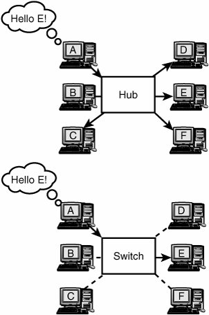
Shared and Nonshared Network Media TopologiesAs mentioned earlier, you must abide by some constraints when constructing very large LAN environments. One item that often is overlooked is the size of the broadcast domain for a LAN segment. Hubs take inbound traffic and broadcast it outbound on all their other ports. This means that each time a node makes a network request, the request is flooded to all other nodes. The more nodes you have on your LAN, the more traffic you have being flooded throughout the LAN segment. If you are running an Ethernet network, all this chatter can keep your LAN segment so busy that other nodes might have trouble finding an opportunity to transmit.
A solution for this problem is the introduction of a switch into the network environment. By deploying a switch in place of a hub, you dramatically reduce the number of flooded packets. Switches don't just blindly repeat network traffic. Instead, they make intelligent port-forwarding decisions based on the addresses they recognize within the packets. The net effect of introducing switches into your environment in place of hubs is that your nodes see very little flooded traffic (unless it is addressed to them) and the contention problem is greatly reduced (see Figure 2.11). Figure 2.11. Switches can centralize wiring and also provide a greater available bandwidth to the network. Note The term broadcast domain is used to describe the total collection of devices that use the same network media, and thus have to contend for access to the media. This is the main reason switches have become the device of choice to replace hubs. Using a switch, the broadcast domain consists of just the switch and the device attached to the switch (if using a half-duplex connection). For a full-duplex connectionin which both the switch and the attached device can transmit data at the same time using separate wiresthe broadcast domain is eliminated, because there is no shared media. Don't forget that you still have the network broadcasts to contend with. Broadcasts get flooded to all ports within a network segment, regardless of whether you use hubs or switches. So always consider the amount of broadcast traffic added to your environment when expanding your LAN. Full-Duplex Versus Half-DuplexThe discussion of shared and nonshared media would not be complete without the mention of full-duplex technologies. Everything that has been covered so far has assumed a half-duplex environment, which means that a node can either receive or transmit but cannot do both at the same time. In a full-duplex environment, a node can transmit and receive at the same time using separate receive and transmit pairs. If you realize that having separate pairs for transmit and receive means that there is no chance for packet collisions, you are absolutely correct! Recent and current Ethernet hardware typically use auto-sensing to determine whether full-duplex or half-duplex connections are in use (virtually all Ethernet adapters and switches in recent years have used full-duplex). However, if you interconnect full-duplex adapters with older adapters, you might need to manually configure the full-duplex adapters to run in a half-duplex mode. If necessary, this is done through the Media Type dialog provided as part of the network adapter's setup program. In Windows XP, use the Advanced tab of the network adapter's properties sheet in Device Manager to access the Media Type dialog. You might ask yourself why a network topology would ever use half-duplex to begin with. The answer is simple: It's historical. Recall that at the time Ethernet was invented it was a bus topology with a coax cable; there was no opportunity for a dedicated transmit and receive pair. Bridged Versus Routed TopologiesThis section reviews bridged and routed topologies to give you a sense of how each technology can be used. BridgingBridges are intelligent network devices that monitor the MAC level (layer 2) addresses within a packet. A bridge creates a table in its memory and stores the MAC address and port address of each network resource that it sees as a source of network traffic, in effect "learning" which ports are connected to a particular node. When a bridge fails to recognize the destination MAC address of a packet it has received, it floods the packet to all its ports. When a bridge knows the destination port, it just forwards the packet to that one port. Using this methodology, the bridge quickly accumulates an understanding of where all devices reside from its viewpoint and intelligently forwards traffic. Sounds a lot like the switch that was used earlier to replace the hub technology, doesn't it? Indeed, switches are basically just high-speed bridges with a high port density. This has made the need for dedicated bridges all but nonexistant. RoutingRouters are intelligent network devices that work at the Network level (layer 3). It is at this level that protocols such as TCP/IP, IPX/SPX, and AppleTalk are defined. Routers understand the routing topology; that is, they have an idea where all LAN segments reside. They perform routing tasks by using special "routing protocols" to communicate with other routers within a network.
Routers intelligently forward packets based on the destination segment information contained in the network protocol within a packet. A nice feature of routing is that routers do not propagate broadcasts. Broadcasts stay within a network segment, and routers are the devices that segment the network. VLANsWhen manufacturers first came out with hubs, these devices could support only one network segment. But what if you needed to support multiple network segments out of the same wiring closet? The answer was simple: You needed more hubs! Virtual local area networks (VLANs) solved this problem by providing trunking protocols that allowed the traffic of multiple LAN segments to be multiplexed across the same riser cable. After the traffic was received, the switch or hub device demultiplexed the traffic and forwarded it to the appropriate ports. In this manner, many subnets could be supported out of a single network component, and collision-domain size could be controlled by carving a large LAN into several small VLANs. A side benefit of VLANs is the security gained by being able to partition workgroups with sensitive security needs off onto their own VLAN for an extra measure of protection.
Layer-3 SwitchingLayer-3 switching is a hybrid technology that combines the speed of a switch with the LAN segment analysis of a router to make packet forwarding decisions. Layer-3 switching is the best of both worlds because you get the broadcast isolation and segmenting capabilities of a router, yet you have the lightning-fast forwarding decisions of a wire-speed switching device. A layer-3 switch can typically forward a packet 1020 times faster than a router! |


EAN: 2147483647
Pages: 411