The Importance of Frame Relay and the X.25 Interface
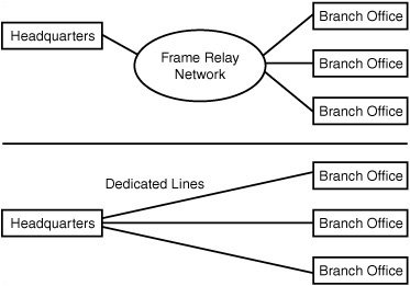
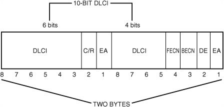
| The X.25 protocol defines an interface for delivering information to a packet-switched network and does not make any assumptions about the method used to carry the actual data from one place to another. Or, to put it another way, X.25 is not a transport protocol. It is an interface that can be adapted to different kinds of network transport protocols. X.25, which has been around for more than 20 years, was developed to allow connection to various public networks, such as CompuServe and Tymnet, and it provides for speeds of up to 56Kbps. Frame Relay is similar to X.25 except that it uses digital connections instead of the analog connections that X.25 was designed for. Although X.25 can be considered a "dying" technology, Frame Relay use continues to grow. Frame Relay can operate at much higher speeds (up to 1.544Mbps) than X.25 because of the digital nature of Frame Relay, which is usually offered over a T1 or fractional T1 line. The digital nature of the line allows fewer errors than the analog system, and Frame Relay can operate faster than other technologies because it does not perform any actual error correction. When a frame error is detected, the frame is dropped. It is up to the endpoints to detect, through some higher-level protocol, that an error has occurred. If an error is found in the frame, or if the network is too busy, the frame is dropped. This is similar to the way the IP functions. Frame Relay does its best to get the frame to its endpoint in the connection, but it does not notify the starting point of the connection if an error occurs. Because Frame Relay doesn't have to worry about reporting errors (which can occur anywhere along the path, at any switch) back to the sender, it can switch traffic at a faster rate. With today's fast CPUs and digital lines (which are less prone to errors than analog lines), it only makes sense to let higher-level protocols take care of detecting and remedying errors. Because Frame Relay is a packet-switched technology, you must pay for only the bandwidth you expect to use. Instead of paying for the full cost of a T1 line between two geographically distant offices, you can use Frame-Relay services. The carrier mixes traffic from various sources and transmits it over the line so that Frame Relay represents a shared-medium technology. The downside is that it's always possible that the bandwidth you need might not be available when you need it. Just as you sometimes get a circuit-busy message when you try to place a telephone call during a peak holiday period, the same thing can happen if traffic from multiple users of a carrier's Frame-Relay service must transfer large amounts of data at the same time. For this reason, when you purchase Frame-Relay services, you get a guaranteecalled the committed information rate (CIR)of the amount of available bandwidth that the carrier expects to be capable of providing. You might be able to get higher throughput rates than that guaranteed by the CIR, but there is always the possibility that, occasionally, you might not achieve rates that are guaranteed by the CIR. It is important to monitor your use in a high-traffic environment to be sure you are getting what you paid for. Frame Relay also can reduce the number of physical connections you need at a site, which can make it a better choice than dedicated point-to-point lines. For example, if you have multiple branch offices, you could use a dedicated T1 (or Fractional T1) line to connect each office to the main headquarters. Or you could use Frame Relay at each branch office, using only a single physical connection back at the main office. Traffic from all the branch offices is lumped together on this incoming Frame Relay line, so you don't need a separate physical dedicated line going to each branch office (see Figure 15.5). Figure 15.5. Using Frame Relay can reduce the number of physical connections required when compared to dedicated lines. Frame Relay is similar to ATM in that it is a packet-switched technology. However, ATM uses a fixed sized for its cells, whereas Frame Relay packets are variable (similar to Ethernet frames). Packet switching in a Frame Relay network is done using virtual circuits, which are logical paths through the Frame Relay network. Note Some vendors of Frame-Relay services offer much faster capabilities, up to 45Mbps, using T3 lines. The Frame Relay HeaderFrame Relay also has a lower overhead than traditional network technologies, such as Ethernet. The Frame Relay header is only 25 bytes long. In Figure 15.6, you can see that the header doesn't contain a whole lot of information. Figure 15.6. The Frame Relay header contains the DLCI (Data Link Connection Identifier) that identifies the connection. The following fields appear in Figure 15.6:
The DLCI field is a 10-bit number used to specify the virtual circuit number for the connection. The DLCI identifies the particular port to which the local network is attached in the Frame Relay equipment. Throughout the network, this number is used to designate the endpoint of the connection. When using a PVC, the network administrator must set up routing tables in the switches that make up the network. When a frame comes in one port, it is a simple matter to look up the DLCI in a table and then quickly switch the frame to an outgoing port that can take it to another switch, where the process is repeated, or to its eventual destination. Note that if a switch receives a frame that has a DLCI value that is not found in the switch's routing table, the frame is discarded. If this sounds like a simple mechanism for getting a data frame from one point to another, it is. In addition to the short header, the Frame Relay packet also has a frame check sequence (FCS) value calculated to ensure the integrity of the packet, which is placed at the end of the frame. The switch can recalculate this value when it receives a frame and, if the newly calculated value does not match the value stored in this field, the frame is assumed to have become corrupted and is dropped. Network congestion also can cause a packet to be dropped. After a switch's buffers are full, incoming frames are dropped until buffer space becomes available again. However, Frame Relay does provide some signaling mechanisms that can be used to help control network congestion. Frame Relay also provides for signaling to set up an SVC. Both of these signaling mechanisms, however, are optional components and vendors don't have to implement them. Remember that the higher-level protocol (such as TCP/IP) can detect when its data segments have not been acknowledged and retransmit any data that is dropped along the virtual circuit path. Network Congestion SignalingThree methods can be used to help prevent network congestion:
The Explicit Congestion Notification method uses 2 bits in the header: the FECN (Forward Explicit Congestion Notification) and BECN (Backward Explicit Congestion Notification) bits. The FECN bit is used to tell nodes farther along the path (forward) that congestion is occurring. Based on such things as the switch's buffer use and the length of frames waiting in a queue, a switch can detect that congestion probably is going to occur before it must start dropping packets. When this happens, the switch sets the FECN bit in a packet to 1 (the default is 0) and then sends the packet on to the next switch. In this manner, switches downstream from the switch approaching congestion are notified of the condition. Similarly, the BECN bit is used to notify upstream sources that a network congestion condition is rapidly becoming a possibility. It does this not by returning packets sent from that source, but by watching for packets traveling in the opposite direction that are already addressed to that source. The BECN bit is set to 1 (again, the default is 0) in these packets. Thus, when a source sending out a lot of traffic starts to receive packets back from other switches, it can check this bit to determine whether packets are being transmitted too fast. Implicit Congestion Notification is not performed by the Frame Relay switches. Instead, it means that the higher-level protocols, such as TCP, can detect that packets are not being acknowledged, take appropriate action to retransmit them, and, depending on the higher-level protocol, possibly slow down the transmission rate. Referring to Figure 15.6, notice that another field, Discard Eligibility (DE), also can be present in a Frame Relay packet. This field is used to determine which packets should be dropped when a congestion condition occurs. Remember that the Frame Relay provider contracts to give you a CIR. Yet when the network is not busy, usually you can use more bandwidth. However, after you begin to send out data at a rate that is greater than the CIR you have contracted for, the DE bit is set to 1 (the default is 0). When a switch needs to drop packets due to network congestion, those packets that have the DE field set to 1 are the first to go! If discarding those packets doesn't solve the problem, any packet can be dropped. When properly implemented, however, this mechanism lets a switch drop packets that probably are the source of the congestion in the first place: those that are sending at a rate above their contracted CIR. The Local Management Interface Signal MechanismAnother optional signaling mechanism that can be used in a Frame-Relay network is called the Local Management Interface (LMI) specification, of which there are several versions. However, the basic mechanism employed is to use nondata management frames to report the status of an interface or a virtual circuit. For example, a management frame can be used to send a keepalive signal, indicating that, although there isn't a lot of traffic flowing through the interface, the connection is still active. Another management frame can be used to report on the valid DLCIs for a particular interface. Finally, a management frame can be used to indicate the status of a virtual circuit (it's congested, for example). Using Switched Virtual Circuits (SVCs)Originally, most Frame Relay equipment was made to allow for the creation of PVCs. This requires that a network administrator of the Frame-Relay network set up routing tables so that a permanent connection exists between the two endpoints of a connection. This is a general principle, in that alternative routes can be used occasionally, but basically a PVC is an always-on, same-path type of connection. An SVC is more like a telephone call; it's an on-demand path created for the duration of the datatransfer session. After it has been used, the virtual circuit is torn down and doesn't stay in a switch's routing table like the DLCI entries for a PVC. When an SVC needs to be created, the destination is notified of the need, and, if it is willing to accept the circuit, a path is created through the Frame-Relay network for the SVC (call setup). When the circuit is no longer needed, either side of the connection can notify the network to terminate the circuit. The advantage of using an SVC is that you have to pay only for what you use. It's less expensive than maintaining a PVC that doesn't have a constant rate of traffic. SVCs also can be used in conjunction with PVCs. You can use PVCs for your basic network traffic that flows at a predictable rate, and create or tear down SVCs as needed to handle additional traffic. The methods used for signaling to set up and terminate SVCs is beyond the scope of this book, and this is a subject that should be pursued if you are an administrator of a Frame-Relay network. For the end user, however, the mechanisms used for call setup and termination aren't that important. You might want to visit the Frame Relay Forum's Web site, which contains a wealth of information on the technical details involved in signaling, as well as documents about proposed new methods and features for Frame-Relay networks. Possible Problems Using Frame RelayYou might encounter the following problems when using Frame Relay:
The Frame Relay Forum defined several metrics that can be used to determine the quality of service in a Frame-Relay network. These metrics, which can be found in the forum's FRF.13 Service Level Definitions Implementation Agreement, are listed here:
When reviewing the Service Level Agreement (SLA) that your Frame-Relay provider offers, use these metrics to help you understand what kind of commitment the vendor is making. With these metrics, the vendor might further qualify them based on the CIR as opposed to bursts allowed by the agreement. For example, it would be unreasonable to expect to receive the same kind of delivery ratio for bursts of high-volume traffic that you receive for traffic that flows through the network at the rate guaranteed by the CIR. When you review the SLA, be sure you understand how each metric will be measured. Does the vendor use statistics provided by its own switch (and will the vendor allow you access to these statistics?), or does the vendor use an RMON probe or SNMP MIB to define the metrics? What portion of the connection is to be measured for metrics: end-to-end or switch to switch? |
EAN: 2147483647
Pages: 411