5.4 Subcarrier Permutations in WiMAX OFDMA PHY
5.4 Subcarrier Permutations in WiMAX OFDMA PHY
Distributing the subcarriers over the subchannels is a very open problem with many parameters to consider: mobility, AAS support, different optimisation criterions, etc. The 802.16 standard and its amendment 802.l6e provide full details for the many subcarriers permutations defined. In this section, we briefly describe the subcarriers permutations defined in Mobile WiMAX OFDMA PHY and detail one of these permutations.
5.4.1 The Main Permutation Modes in OFDMA
Subtracting the guard subcarriers and the DC subcarrier from NFFT gives the set of ‘used’ subcarriers Nused. For both the uplink and downlink, these subcarriers are allocated as pilot subcarriers and data subcarriers according to one or another of the defined OFDMA permutation modes.
Two families of distribution modes can be distinguished:
-
Diversity (or distributed) permutations. The subcarriers are distributed pseudo-randomly. This family includes: FUSC (Full Usage of the SubChannels) and PUSC (Partial Usage of the SubChannels), OPUSC (Optional PUSC), OFUSC (Optional FUSC) and TUSC (Tile Usage of SubChannels). The main advantages of distributed permutations are frequency diversity and intercell interference averaging. Diversity permutations minimise the probability of using the same subcarrier in adjacent sectors or cells. On the other hand, channel estimation is not easy as the subcarriers are distributed over the available bandwidth.
-
Contiguous (or adjacent) permutations. These consider a group of adjacent subcarriers. This family includes the AMC (Adaptive Modulation and Coding) mode. This type of permutation leaves the door open for the choice of the best-conditions part of the bandwidth. Channel estimation is easier as the subcarriers are adjacent.
Mandatory permutation modes of the presently defined mobile WiMAX profiles are:
-
for the downlink: PUSC, FUSC and AMC;
-
for the uplink: PUSC and AMC.
5.4.2 Some OFDMA PHY Definitions
5.4.2.1 Subchannels and Pilot Subcarriers
A subchannel is the minimum transmission unit in an OFDMA symbol. Each of the permutation modes of OFDMA has its definition for a subchannel. There is also a difference between allocation of the data and pilot subcarriers in the subchannels between the different possible permutation modes:
-
For (downlink) FUSC and downlink PUSC, the pilot tones are allocated first. What remains are data subcarriers, which are divided into subchannels that are used exclusively for data.
-
For uplink PUSC, the set of used subcarriers is first partitioned into subchannels and then the pilot subcarriers are allocated from within each subchannel.
Thus, in the FUSC mode, there is one set of common pilot subcarriers, while in the uplink PUSC mode, each subchannel contains its own set of pilot subcarriers. For the downlink PUSC mode, there is one set of common pilot subcarriers for each major group including a set of subchannels (see below).
5.4.2.2 Slot and Burst (Data Region)
A slot in the OFDMA PHY has both a time and subchannel dimension. A slot is the minimum possible data allocation unit in the 802.16 standard. The definition of an OFDMA slot depends on the OFDMA symbol structure, which varies for uplink and downlink. for FUSE and PUSC, and for the distributed subcarrier permutations and the adjacent subcarrier permutation. See Table 5.5 for the different possibilities.
| Permutation mode and communication way | Slot definition |
|---|---|
| Downlink FUSC; downlink OFUSC | 1 subchannel × 1 OFDMA symbol |
| Downlink PUSC | 1 subchannel × 2 OFDMA symbol |
| Uplink PUSC, uplink additional PUSC, downlink TUSCI and TUSCI | 1 subchannel × 3 OFDMA symbol |
| AMC (uplink and downlink) | 1 subchannel × (1, 2 or 3) OFDMA symbol |
In OFDMA, a data region (or burst) is a two-dimensional allocation of a group of slots. i.e. a group contiguous subchannels, in a group of contiguous OFDMA symbols (see Figure 5.13 and the end of the PUSC section below for an example).
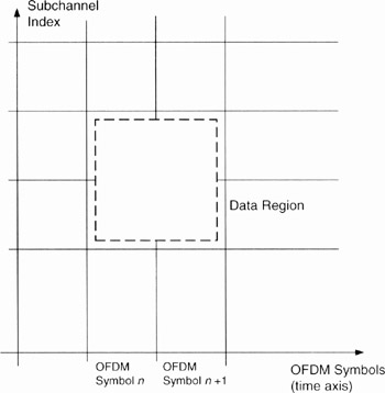
Figure 5.13: Example of the data region that defines the OFDMA burst allocation
5.4.2.3 Segment
A segment is a subdivision of the set of available subchannels, used for deploying one instance of the MAC.
5.4.2.4 Permutation Zone
A permutation zone is a number of contiguous OFDMA symbols, in the downlink frame or the uplink frame, that use the same permutation mode. A downlink frame or an uplink frame may contain more than one permutation zones (see Figure 5.14), providing great malleability for designers.
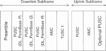
Figure 5.14: Example of different permutation zones in uplink and downlink frames
5.4.3 PUSC Permutation Mode
The global principle of PUSC (Partial Usage of SubChannels) is the following. The symbol is first divided into subsets called clusters (downlink) or tiles (uplink). Pilots and data carriers are allocated within each subset. This allows partial frequency diversity. Some main MAC messages and some PHY subframe fields are transmitted in the PUSC mode: FCH, DL-MAP and UL-MAP (see Chapter 9 for these messages). Downlink PUSC subchannel allocation will now be detailed, which is illustrated by an example.
The global principle of downlink PUSC cluster and subcarrier allocation is illustrated in Figure 5.15. Considering, for example, a 1024-FPT OFDMA Symbol, the number of guard subcarriers + DC carrier is (in thc case of 1024 FFT) 92 + 91 + 1 = 184. Therefore, the number of pilot and data carriers to be distributed is 1024−184 = 840. The parameters of this numerical example are given in Table 5.6.
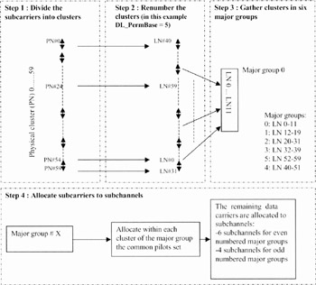
Figure 5.15: Illustration of the downlink PUSC Cluster and subcarrier allocation
| Parameter | FFT Size | BW | G | N | Pilot + data subcarriers | NFFT | fs | Δf |
|---|---|---|---|---|---|---|---|---|
| Value | 1024 | 10MHz | 1/8 | 28/25 | 840 | 1024 | 11.2MHz | 10.9375 kHz |
5.4.3.1 Allocation Steps
Step 1. Divide the Subcarriers into Clusters
After removing the guard and DC subcarriers, the 840 (pilot and data) subcarriers are divided into 60 clusters of 14 adjacent sub carriers each (14 × 60 = 840) (see Figure 5.16). We here mention that a PUSC cluster has nothing to see with a cluster of cells (see Chapter 4). The Physical Cluster number is between 0 and 59. Pilot subcarriers are placed within each cluster depending on the parity of the OFDMA symbols, as shown in Figure 5.17.

Figure 5.16: Cluster allocation

Figure 5.17: Cluster structure. (Based on Reference [2].)
Step 2. Renumber the Clusters
The clusters are renumbered with Logical Numbers (LNs). The cluster LN is also between 0 and 59. In order to renumber the clusters, the DL_PermBase parameter is used.
DL_PermBase is an integer ranging from 0 to 31, which can be indicated by DL_MAP for PUSC zones (see Chapter 9).
The clusters are renumbered to LN clusters using the following formula (denoted Formula (0) in the following):
In the case of the first downlink zone (containing the FCH and DL-MAP), or Use All SC Indicator = 0 in STC_DL_Zone_IE (see Chapter 9 for STC_DL_Zone_IE):

where the Renumbering sequence (j) is the jth entry of the following vector:
[6, 48, 37, 21, 31, 40, 42, 56, 32, 47, 30, 33, 54, 18, 10, 15, 50, 51, 58, 46, 23, 45, 16, 57, 39, 35, 7, 55, 25, 59, 53, 11, 22, 38, 28, 19, 17, 3, 27, 12, 29, 26, 5, 41, 49, 44, 9, 8, 1, 13, 36, 14, 43, 2, 20, 24, 52, 4, 34, 0]
It should be remembered that, for 1024-FFT, Nclusters = 60, so the above vector has 60 elements.
Step 3. Gather Clusters in Six Major Groups
The renumbered clusters are then gathered in six major groups, using the LN, as shown in Table 5.7.
| Group | Cluster index |
|---|---|
| o | LN 0–11 |
| 1 | LN 12–19 |
| 2 | LN 20–31 |
| 3 | LN 32–39 |
| 4 | LN 40–51 |
| 5 | LN 52–59 |
Step 4. Allocate Subcarriers to Subchannels
In the downlink PUSC the number of subchannels per OFDMA symbol is 30, numbered from 0 to 29. A subchannel is made of 24 data subcarriers, which represents the data subcarriers of two clusters. It can be verified that: 30 × 24 = 720 data subcarriers (720 data subcarriers + 30 × 4 pilot subcarriers = 840 subcarriers). For the downlink PUSC, each major group is used separately in order to have a number of subchannels; i.e. one subchannel does not have subcarriers in more than one major group. In addition, all the subcarriers of one subchannel belong to the same OFDMA symbol.
The pilot and data subcarrier allocations to subchannels are done as follows. The pilot subcarriers are allocated first within each cluster, placed as shown in Figure 5.17. In the downlink puse, there is one set of common pilot subcarriers in each major group. The remaining data subcarriers are first renumbered from 0 to 143 or 95 depending on the parity of the major group. Then the subcarriers are allocated within each subchannel using the following formula:

where NNsuhchanncls is the number of subchannels in the partitioned major group, equal to 4 or 6. depending on the parity of the major group; subcarrier(k,s) is the subcarrier index of subcarrier k, varying between 0 and 23, in subchannel s, whose value ranges between 0 and 143 or 95 depending on the parity of the major group; s is the subchannel index varying between 0 and 29, and so
![]()
where Nsubcarriers is the number of data subcarriers allocated to a subchannel in each OFDMA symbol (= 24 in this case); Ps[j] is the series obtained by rotating the basic permutation sequence cyclically to the lefts times, which is given in the following: in the case of an odd numbered major group the basic permutation is PermutationBase6 (3,2,0,4,5,1), while for an even numbered major group it is PermutationBase4 (3,0,2,1).
For even numbered major groups, the 12 clusters contain the data subcarriers of 6 subchannels:
-
6 × 24 = 144 data subcarriers;
-
144 + 6 × 4 = 168 (data and pilot) subcarriers.
For odd numbered major groups, the 8 clusters contain the data subcarriers of 4 subchannels:
-
4 × 24 = 96 data subcarriers;
-
96 + 4 × 4 = 112 (data and pilot) subcarriers.
The correspondance between subchannels and major groups is given in Table 5.8 (for 1024-FFT OFDMA). A numerical example of the downlink PUSC allocation is proposed below.
| Major group (subchannel group) | Subchannel range |
|---|---|
| 0 | 0–5 |
| 1 | 6–9 |
| 2 | 10–15 |
| 3 | 16–19 |
| 4 | 20–25 |
| 5 | 26–29 |
5.4.3.2 Numerical Example
Based on comprehension of the IEEE 802.16 standard, a numerical example is proposed. A start is made with step 4, the previous steps having fixed values. The aim is to find the 24 physical (data) subcarriers of subchannel 16 of the downlink PUSC. It is assumed that DL_PermBase = 5 (indicated in the DL-MAP MAC Management Message) and that the OFDMA symbol considered is odd numbered.
Subchannel 16 is in major group 3, as shown in Table 5.8. Therefore, basic permutation sequence = (3,0,2,1), Nsubcarriers = 24 (this is the case for all subchannels) and Nsubchannels = 4 (odd numbered major group). In major group 3, the correspondence between the Logical Number (LN) and the original Physical Number (PN) is obtained by applying the equation of step 2, using the LN and its position in the renumbering sequence. Thus the correspondence is as shown in Table 5.9.
| Cluster LN | Logical subcarrier index | Cluster PN formula (0) | Cluster physical subcarrier index |
|---|---|---|---|
| 32 | 0–13 | 3 | 42–55 |
| 33 | 14–27 | 6 | 84–97 |
| 34 | 28–41 | 53 | 742–755 |
| 35 | 42–55 | 20 | 280–293 |
| 36 | 56–69 | 45 | 630–643 |
| 37 | 70–83 | 57 | 798–811 |
| 38 | 84–97 | 28 | 392–405 |
| 39 | 98–111 | 19 | 266–279 |
Table 5.10 depicts nk and the physical subcarrier index corresponding to the each subcarrier k in subchannel s (= 16). For each subcarrier, the LN cluster of this subcarrier major group is used in order to find the physical subcarrier index (Table 5.9 is also used). For the pilot set for major group 3, using Table 5.9 values and the principle of Figure 5.16 gives the physical indices of each cluster pilot subcarriers. These indices are proposed in Table 5.11.
| Logical subcarrier index (k) in the considered subchannel (s = 16) | nk (formula (5.2)) | Logical subcarrier index in the major group (formula (5.1)) and corresponding cluster LN (using Table 5.9) | Physical subcarrier index (using Table 5.9 and Figure 5.17) | |
|---|---|---|---|---|
| Subcarrier | Cluster LN | |||
| 0 | 16 | 67 | 37 | 805 |
| 1 | 17 | 69 | 37 | 807 |
| 2 | 18 | 76 | 38 | 396 |
| 3 | 19 | 78 | 38 | 398 |
| 4 | 20 | 83 | 38 | 403 |
| 5 | 21 | 85 | 39 | 267 |
| 6 | 22 | 92 | 39 | 274 |
| 7 | 23 | 94 | 39 | 276 |
| 8 | 0 | 3 | 32 | 45 |
| 9 | 1 | 5 | 32 | 47 |
| 10 | 2 | 12 | 32 | 55 |
| 11 | 3 | 14 | 33 | 86 |
| 12 | 4 | 19 | 33 | 91 |
| 13 | 5 | 21 | 33 | 93 |
| 14 | 6 | 28 | 34 | 746 |
| 15 | 7 | 30 | 34 | 749 |
| 16 | 8 | 35 | 34 | 753 |
| 17 | 9 | 37 | 35 | 281 |
| 18 | 10 | 44 | 35 | 288 |
| 19 | 11 | 46 | 35 | 290 |
| 20 | 12 | 51 | 36 | 633 |
| 21 | 13 | 53 | 36 | 635 |
| 22 | 14 | 60 | 36 | 643 |
| 23 | 15 | 62 | 37 | 800 |
| Cluster PN | Pilot subcarrier physical index |
|---|---|
| 3 | 42 and 54 |
| 6 | 84 and 96 |
| 53 | 742 and 754 |
| 20 | 280 and 292 |
| 45 | 630 and 642 |
| 57 | 798 and 810 |
| 28 | 392 and 404 |
| 19 | 266 and 278 |
5.4.3.3 One Subchannel Instantaneous Data Rate
The data rate corresponding to one slot (equal to one subchannel over two slots) will now be computed. One OFDMA symbol duration is 102.9 μs (see the numerical example parameters in Table 5.6 in Section 5.4.3 and Section 5.2.4 computations). A slot contains 48 subcarriers and then 48 modulation symbols. The instantaneous data rate of one subchannel can then be computed. The obtained values (no repetition) are given in Table 5.12.
| BPSK 1/2 | QPSK 1/2 | QPSK 3/4 | 16-QAM 1/2 | 16-QAM 3/4 | 64-QAM 2/3 | 64-QAM 3/4 | |
|---|---|---|---|---|---|---|---|
| Instantaneous data rate | 116.6 | 233.3 | 349.8 | 466.5 | 699.75 | 932.9 | 1049 |
5.4.3.4 Use of Subchannels to Allocate Bandwidth
A lot is, by definition, in the downlink PUSC, made of 48 subcarriers:

The data region information indicated in a DL-MAP MAC Management Message for an (OFDMA) downlink user is:
-
OFDMA symbol offset. The offset of the OFDMA symbol in which the burst starts, measured in OFDMA symbols from the beginning of the downlink frame in which the DL-MAP is transmitted.
-
Subchannel offset. The lowest index OFDMA subchannel used for carrying the burst, starting from subchannel 0.
-
Number of OFDMA symbols. The number of OFDMA symbols that are used (fully or partially) to carry the downlink PHY burst. The value of the field is a multiple of the slot length in symbols.
-
Number of subchannels. The number of subchannels with subsequent indexes used to carry the burst.
The parameter DL_PermBase is indicated in the zone switch IE (Information Element) in a DL-MAP, indicating a given permutation zone.
5.4.3.5 Uplink PUSC
For uplink PUSC, subchannels are built based on Tiles (see Figure 5.18). An uplink PUSC slot is made of one subchannel over three OFDMA symbols.
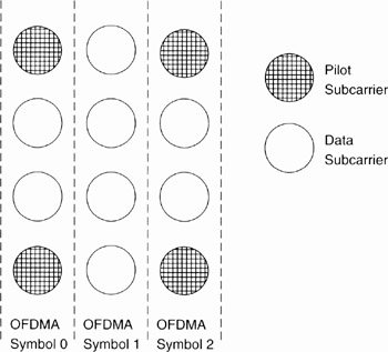
Figure 5.18: Uplink PUSC Tile is made of 12 subcarriers. (Based on Reference [1].)
5.4.4 FUSC Permutation Mode
The global principle of FUSC (Full Usage of SubChannels) is close to PUSC. The difference is that there is no cluster (or tile) partitioning of subcarriers before subchannel allocation. Each subchannel subcarrier can be any where in the bandwidth.
In FUSC, the number of pilot and data carriers to be distributed is different from PUSC. The number of guard subcarriers + the DC carrier (in the case of 1024 FFT) is 87 + 86 + 1 = 174. Therefore, the number of pilot and data carriers to be distributed is 1024 − 174 = 850.
There are two constant pilot sets and two variable pilot sets (depending on the OFDMA symbol parity). Each segment uses both sets of variable/constant pilot sets.
For the FUSC mode, a 1024-FFT OFDMA symbol is considered. This symbol is divided into 16 subchannels of 48 subcarriers each, thus using all of the 16 × 48 = 768 data subcarriers. The data subcarriers are first divided into groups of contigucus subcarriers. Then each subchannel is constructed using one subcarrier of each group, as shown in Figure 5.19.
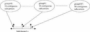
Figure 5.19: Illustration of a FUSC subchannel
5.4.5 AMC Permutation Mode
In the AMC (Adaptive Modulation and Coding) mode, a subchannel is made of adjacent sub-carriers. The basic allocation unit for downlink and uplink AMCs is the bin, which is a set of nine adjacent (or contiguous) subcarriers within an OFDMA symbol, as shown in Figure 5.20. Contrary to distributed subchannel allocation techniques (such as PUSC), AMC pilot and data subcarriers are assigned fixed positions. This allows easy support of the AAS (Adaptive Antennas System).
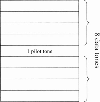
Figure 5.20: Bin structure
An AMC slot is made of six bins or, equivalently, 48 data subcarriers and 6 pilot subcarriers. A group of four consecutive rows of bins in an OFDMA symbol is called a physical band. For 1024-FFT, the number of physical bands is then 24 (24 × 4 × 9 = 864 data and pilot subcarriers to be distributed). A grouping of physical AMC bands is a logical band. The maximum number of logical bands is specified in the Format configuration IE and can be a maximum of 24. For example, if the available physical bands are distributed over three logical bands, for 1024-FFT, a logical band is made of eight physical bands. The global principle of AMC subcarrier allocation is illustrated in Figure 5.21.
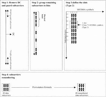
Figure 5.21: Illustration of the global principle of AMC subcarrier allocation (the number of guard subcarriers is for 1024-FFT)
There are four types of AMC slots (48 subcarriers), which are combinations of six contiguous bins:
-
Type 1 (default type). A slot consists of six consecutive bins within one OFDMA symbol.
-
Type 2. A slot consists of 2 bins × 3 OFDMA symbols. This type is the only mandatory one according to presently defined Mobile WiMAX profiles.
-
Type 3. A slot consists of 3 bins × 2 OFDMA symbols.
-
Type 4. A slot consists of 1 bin × 6 OFDMA symbols.
The type is referred to as N × M, where N is the number of bins and M the number of symbols.
5.4.5.1 AMC (or Regular AMC) and Band AMC
AMC allocations can be made by two mechanisms:
-
Regular AMC (or, simply, AMC) is allocated by a subchannel index reference using DL-MAP and UL-MAP.
-
Band AMC is part of the HARQ map included with the normal map in the downlink or uplink zone. For Band AMC, the six contiguous bins of a Band AMC slot must be in the same logical band.
5.4.6 TUSC Permutation Mode
The IEEE 802.16e amendment defined two new optional permutation modes for the down-link: TUSC1 (Tile Usage of SubChannels) and TUSC2. TUSC1 and TUSC2 are dedicated to the AAS zone in an FDMA frame. The general principle is close to the uplink PUSC. TUSCI and TUSC2 are not mandatory in presently defined mobile WiMAX profiles.
EAN: 2147483647
Pages: 124