Firewall Technologies
| This section focuses on the technologies used in various firewalls and how they work. The firewall taxonomy in Figure 2-1 shows the general types of firewalls. This section focuses more on the underlying technologies that devices that fall into those types utilize. In some cases, one technology discussed here can fall into multiple types in the taxonomy tree. The focus is on a wide range of firewall technologies, including the following:
Now, you might be thinking, "Wait, I thought there were three firewall products: software based, appliance based, and integrated." The firewall technologies discussed in this section may be used by any of the three basic physical firewalls. Indeed, these technologies simply allow us to define a firewall in a more granular fashion. So, for example, an appliance firewall can be further quantified as a stateful firewall. Each of these technologies is examined and discussed to provide you with an understanding of the differences between these technologies, and by extension the firewall devices that utilize these technologies. Each section focuses predominantly on the operation of the firewall in its function as a network security device. Discussion of the redundancy capabilities, performance, and management of specific firewalls is not covered. This section provides a brief introduction to some specific firewalls that subsequent chapters cover in greater detail. Personal FirewallsPersonal firewalls are designed to protect a single host. They can be viewed as a hardened shell around the host system, whether it is a server, desktop, or laptop. Typically, personal firewalls assume that outbound traffic from the system is to be permitted and inbound traffic requires inspection. By default, personal firewalls include various profiles that accommodate the typical traffic a system might see. For example, ZoneAlarm has low, medium, and high settings that allow almost all traffic, selected traffic, or nearly no traffic, respectively, through to the protected system. In a similar vein, IPTableswhich you can set up as a personal firewall as well as in a network firewall roleduring the setup of the Linux system, enables the installer to choose the level of protection for the system and the customization for ports that do not fall into a specific profile. One important consideration with personal firewalls is centralized management. Some vendors have identified that a significant barrier to deployment of personal firewall on every end system is the need for centralized management so that policies can be developed and applied remotely to end systems and have developed such capabilities within their products. Large enterprises are hesitant to adopt this personal firewall technology for their systems because of the difficulty of maintaining a consistent firewall policy across the enterprise. Packet FiltersPacket filters are network devices that filter traffic based on simple packet characteristics. These devices are typically stateless in that they do not keep a table of the connection state of the various traffic flows through them. To allow traffic in both directions, they must be configured to permit return traffic. Simple packet filters include Cisco IOS access lists as well as Linux's ipfwadm facility to name a few. Although these filters provide protection against a wide variety of threats, they are not dynamic enough to be considered true firewalls. Their primary focus is to limit traffic inbound while providing for outbound and established traffic to flow unimpeded. Example 2-1 shows a simple access list for filtering traffic. This list is based on the network example in Figure 2-2. The access list is applied to the inbound side of the filtering device that connects the LAN to the Internet. Figure 2-2. Simple Access List Sample Network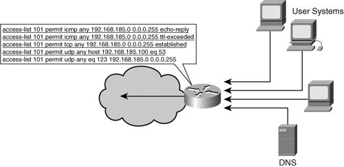 Example 2-1. Simple Access List
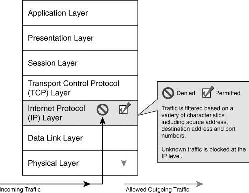
Note that inbound return traffic for DNS (53/UDP) and NTP (123/UDP) are explicitly stated toward the end of the filter list, as are Internet Control Message Protocol (ICMP) echo-reply and Time-To-Live (TTL)-exceeded responses. Without these statements, these packets would be blocked even though they are in response to traffic that originated in the protected LAN. Finally, note the following rule: access-list 101 permit tcp any 192.168.185.0 0.0.0.255 established This rule is required to allow return traffic from any outside system back to the 192.168.185.0/24 subnet as long as the return traffic has the TCP ACK flag set. Packet filters typically do not have any stateful capabilities to inspect outbound traffic and dynamically generate rules permitting the return traffic to an outbound flow. Figure 2-3 shows a simple packet-filtering firewall. Figure 2-3. Packet-Filtering Firewall NAT FirewallsA distinct firewall that existed for a short period is the Network Address Translation (NAT) firewall. In today's firewall market, NAT is a part of almost every firewall product available. From the lowliest SOHO firewall such as the Linksys BEFSX41 to the high-end enterprise PIX 535, NAT is now a function of a firewall. NAT firewalls automatically provide protection to systems behind the firewall because they only allow connections that originate from the inside of the firewall. The basic purpose of NAT is to multiplex traffic from an internal network and present it to a wider network (that is, the Internet) as though it were coming from a single IP address or a small range on IP addresses. The NAT firewall creates a table in memory that contains information about connections that the firewall has seen. This table maps the addresses of internal systems to an external address. The ability to place an entire network behind a single IP address is based on the mapping of port numbers on the NAT firewall. For example, consider the systems shown in Figure 2-4. Figure 2-4. NAT Firewall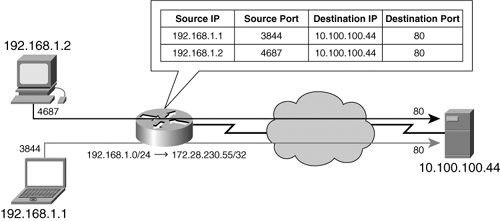 The hosts on the "inside" of the NAT firewall (192.168.1.1 and 192.168.1.2) are both trying to access the web server 10.100.100.44. Host 192.168.1.1 opens up TCP port 3844 and connects to the web server 10.100.100.44 at TCP port 80. Host 192.168.1.2 opens TCP port 4687 and connects to the web server 10.100.100.44 at TCP port 80. The NAT firewall is configured to translate the entire 192.168.1.0/24 network to the single IP address 172.28.230.55. When the firewall sees the outbound connections, it rewrites the IP layer information in the traffic and replaces 192.168.1.1 and 192.168.1.2 with the single IP address 172.28.230.55. Internally, the NAT firewall maintains a table that keeps track of the traffic flows and translates both 192.168.1.1 and 192.168.1.2 to the IP address 172.28.230.55. It does this by means of network sockets that uniquely identify a given connection. For the example shown in Figure 2-4, there are two unique sockets: 192.168.1.1:3844 and 192.168.1.2:4687. When this traffic is seen by the firewall, the NAT process replaces the 192.168.1 network addresses with the 172.28.230.55 address. Table 2-1 shows this process.
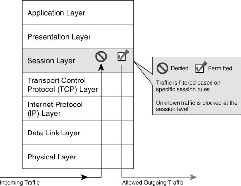
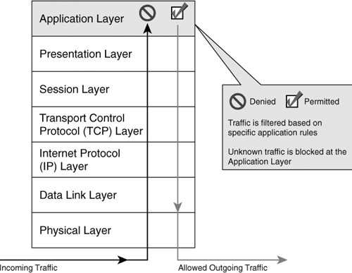
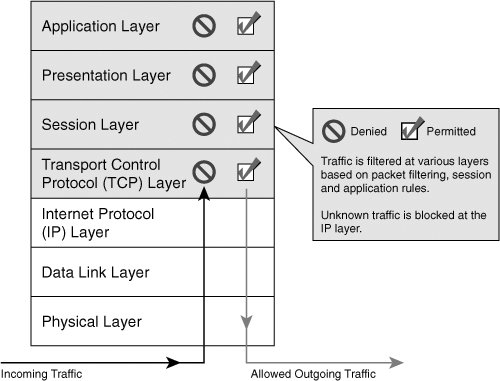
The last entry in the table shows what a NAT firewall does when a specific source port is already taken by a previous connection. In this case, the client 192.168.1.1 is attempting to make a second connection to the web server 10.100.100.44. The client opens a connection on TCP port 4687; however, TCP port 4687 on the NAT firewall is already being used by the connection for the client 192.168.1.2. In this case, the NAT firewall changes not only the source IP address but also the source port and keeps that mapping in its translation table. Circuit-Level FirewallsCircuit-level firewalls work at the session layer of the OSI model and monitor "handshaking" between packets to decide whether the traffic is legitimate. Traffic to a remote computer is modified to make it appear as though it originated from the circuit-level firewall. This modification makes a circuit-level firewall particularly useful in hiding information about a protected network but has the drawback that it does not filter individual packets in a given connection. Figure 2-5 shows an example of a circuit-level firewall. Figure 2-5. Circuit-Level Firewall Proxy FirewallsA proxy firewall acts as an intermediary between two end systems in a similar fashion as a circuit-level gateway. However, in the case of a proxy firewall, the interaction is controlled at the application layer, as shown in Figure 2-6. Proxy firewalls operate at the application layer of the connection by forcing both sides of the conversation to conduct the communication through the proxy. It does this by creating and running a process on the firewall that mirrors a service as though it were running on an end system. To support various services, the proxy firewall must have a specific service running for each protocol: a Simple Mail Transport Protocol (SMTP) proxy for e-mail, a File Transfer Protocol (FTP) proxy for file transfers, and a Hypertext Transfer Protocol (HTTP) proxy for web services. Figure 2-6. Proxy Firewall Whenever a client wants to connect to a service on the Internet, the packets making up the connection request are processed by the specific proxy service for that protocol before being forwarded to the target system. Packets returning from the server on the Internet are similarly processed by the same proxy service before being forwarded to the internal system. In many proxy firewalls, a generic proxy service can be used by services that do not have a service specifically tailored to their needs. However, not all services can use this generic proxy. If there are no proxy capabilities for a specific service running on the firewall, no connection to outside servers running that service is possible, or the firewall utilizes other technologies such as circuit-level filtering to filter the connection. Because of their inspection capabilities, proxy firewalls can look much more deeply into the packets of a connection and apply additional rules to determine whether a packet should be forwarded to an internal host. The disadvantages of a proxy firewall can be in their complex configuration as well as their speed. Because the firewalls look deep into the application, they can introduce delay into network connections. Finally, if there is no specific proxy service for a particular network application and it cannot be made to work with a generic proxy service and the firewall cannot perform other methods of filtering, you cannot put that behind the firewall. Most modern firewalls include basic proxy server architecture in their operation by providing some form of proxy capabilities. For example, PIX OS 6 and earlier had the fixup command, and IPF provided an FTP proxy service to handle active FTP connections. Stateful FirewallsModern stateful firewalls combine aspects and capabilities of NAT firewalls, circuit-level firewalls, and proxy firewalls into one system. These firewalls filter traffic initially based on packet characteristics like the packet-filtering firewall but also include session checks to make sure that the specific session is allowed. Unlike proxy or circuit-level firewalls, stateful firewalls are typically designed to be more transparent (like their packet-filtering and NAT cousins). However, they include proxy-filtering aspects by inspecting the application layer data as well through the use of specific services. This feature is best exemplified through PIX application-inspection capabilities (through the use of the fixup command in PIX OS 6 and the inspect command in PIX OS 7), which allow the PIX to support such protocols as FTP, SMTP, H.323, and many others. Figure 2-7 depicts stateful firewalling. Figure 2-7. Stateful Firewall Stateful firewalls are more complex than their constituent component firewalls; however, nearly all modern firewalls on the market today are stateful firewalls and represent the baseline for security in today's networks. Transparent FirewallsTransparent firewalls (also known as bridging firewalls) are not a completely new firewall but rather a subset of stateful firewalls. Whereas nearly all firewalls operate at the IP layer and above, transparent firewalls sit at Layer 2, the data link layer, and monitor Layer 3+ traffic. Additionally, the transparent firewall can apply packet-filtering rules like any other stateful firewall and still appear invisible to the end user. In essence, the transparent firewall acts as a filtering bridge between two network segments. It represents an excellent way of applying a security policy in the middle of a network segment without having to apply a NAT filter. The benefits of a transparent, bridging firewall fall into three general categories:
The bridging firewall requires no changes to the underlying network, which is possible simply because the transparent bridging firewall is plugged in-line with the network it is protecting. Because it operates at the data link layer, no IP address changes are required. The firewall can be placed so as to segment a network subnet between low-security and higher-security systems or to protect a single host if necessary. Because bridging firewalls tend to be simpler than their Layer 3 cousins, they have a lower processing overhead. That lower overhead enables them to provide better performance as well as deeper packet inspection. Finally, their stealth nature stems directly from the fact that they are Layer 2 devices. The network interfaces of bridging firewalls have no IP addresses (other than the management interface) assigned to them and therefore are invisible to an attacker. The firewall cannot be attacked because, basically, it cannot be reached. Virtual FirewallsVirtual firewalls are multiple logical firewalls running on a single physical device. This arrangement allows for multiple networks to be protected by a unique firewall running a unique security policy all in one physical appliance. A service provider can provide firewall services for multiple customers, securing and separating their traffic while managing the entire system on one device. Service providers do so by defining separate security domains for each customer with each domain controlled by a separate logical virtual firewall. Typically, this capability is available only in higher-end firewalls such as the Cisco PIX 525 and 535 as well as the newer ASA line of devices (because of the memory requirements that each virtual firewall needs to operate properly as well as the necessary CPU capabilities). |
EAN: 2147483647
Pages: 147