4.1. Memory and Cache
| < Day Day Up > |
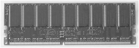
| Figure 4-1 shows the main components of a basic computer system. Notice how the key components are connected by the address bus, control bus, and the data bus. Together these three components make up the "system bus." Figure 4-1. Diagram of a basic computer system. Server performance is substantially increased if the system buses are utilized on every clock cycle. As technical innovations have consistently increased processor speed and capacity, systems designers have been challenged to find ways to keep the system buses fully utilized at every clock cycle. 4.1.1 DRAMIt became apparent early in the evolution of computers that magnetic storage technologies such as tapes and hard disk drives would not be able to keep up with the processor demands because of their slow speed. Memory modules were the innovation that met the challenge to keep up with the increasing speed of processors. Figure 4-2 shows a typical memory module. Figure 4-2. Memory module.
Memory modules use dynamic RAM (DRAM) technology to store and read data for the processor. A DRAM module stores bits of data in capacitors. (A capacitor is an electronic device that can hold an electrical charge.) A capacitor that is holding a charge is equivalent to a binary 1. A capacitor without a charge is equivalent to a binary 0. DRAM is called dynamic RAM because capacitors cannot hold a charge indefinitely. A significant limitation of a DRAM module is that the charge in a capacitor completely drains in a matter of milliseconds if left alone. To keep the data intact, the capacitors must be recharged thousands of times per second. During the recharge process, the memory chip cannot be used to send data to or receive data from the processor. The capacitors on a DRAM module are arranged in grids, sometimes called a memory matrix or a memory chip, as illustrated in Figure 4-3. The rows and columns of the grid are electrically conductive traces etched on the chip. The intersection of a row and column is called a cell. Each cell, which is identified by its row and column address, contains a transistor and a capacitor. Figure 4-3. The memory matrix.
4.1.2 SRAMTo overcome the limitations of DRAM, engineers developed cache. Cache uses a group of transistors arranged as a flip-flop circuit, or latch, to store data. A latch is an electronic circuit that alternates between two states. When current is applied, the latch changes to its opposite state. Figure 4-4 shows a Pentium Pro Processor with a 512KB cache. Figure 4-4. Pentium Pro Processor with 512KB cache (on left).
Cache is known as static RAM (SRAM) because, unlike capacitors, latches do not have to be refreshed. This makes cache much faster than memory. Through the years, engineers have added layers of cache between the processor and memory. Methods have been developed to move cache from the system board to the actual processor. Some Xeon processors, for example, have three levels of cache on the processor. 4.1.2.1 LIMITATIONS OF SRAMDespite its speed, cache does have limitations. First, it is more expensive than DRAM. DRAM stores a bit in a single capacitor, but an SRAM latch requires six to eight transistors to store the same bit. The more transistors, the more expensive the chip is to produce. And second, the transistors in the latches make cache very hot. Special cooling mechanisms, such as heat sinks, must be developed to channel the heat away from the processor. This also increases the cost of SRAM. Figure 4-5 shows an FC-PGA processor on a silver heat sink. Figure 4-5. FC-PGA processor on a silver heat sink.
|
| < Day Day Up > |
EAN: 2147483647
Pages: 278