| One of the most important functions of the IP layer (the network layer of the TCP/IP protocol architecture) is to forward packets between communicating end systems across a number of intermediate systems. (See Figure 16-1.) The determination of the route that packets will take across the Internet and the forwarding of packets towards their destination is called routing. Figure 16-1. Routing within the IP layer in the TCP/IP protocol architecture (protocols in the other layers are examples). 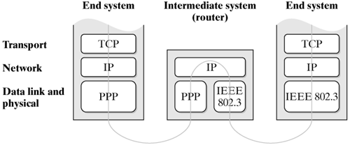
16.1.1 Networks and Routers As was mentioned in Chapter 14, the Internet represents a network of networks. The physical subnetworks built by use of different layer-2 transmission technologies, such as Ethernet, can include a different number of nodes each for example just two nodes connected over a point-to-point link. The IP layer interconnects these subnetworks to form a global network having millions of nodes. Special nodes, which are integrated in all subnetworks that are connected in one place, are used to link these subnetworks; these nodes are called routers. Figure 16-2 shows an example with five local area networks, connected through three routers. Router A also connects the network to the rest of the Internet. The network layer abstracts from lower layers, so it is irrelevant for the communication implemented over IP that the end systems are connected to different LAN types. Figure 16-2. Routers interconnect networks. 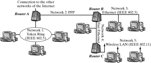
Routers are used both to link local area networks and to connect local area networks to the Internet. In addition, networks in the "core" of the Internet, which normally have a much larger geographic reach, are interconnected and linked to access networks through routers, or even built of direct links between routers ("two-node networks"). Routers are often especially designed for this purpose so-called "dedicated routing devices." However, the Linux kernel also offers the required functionality to let you use a Linux system as a router. 16.1.2 Forwarding and Routing Routers forward IP packets from one physical network to another, where the second network is normally "closer" to the destination network (not necessarily in the sense of geographic distance, but rather from a network-topology view) than the first network. To decide in what direction each packet has to be forwarded, the router requires a certain amount of information about the Internet topology, which it stores locally. This topological knowledge also called forwarding information in the rest of this course can be managed manually for small networks like the example in Figure 16-2, because there is little of it and it changes only if the LAN topology changes. For example, all router B actually needs to know is the end systems in networks 3, 4, and 5. It can send all packets not addressed to end systems in these networks globally towards router A, because the "rest of the Internet" is behind router A. In the core area of the Internet, the situation is not that simple. Rather than a small LAN, there is a large area of the entire Internet behind a network interface of a router. The knowledge required to be able to forward IP packets with arbitrary addresses in the correct direction is much more extensive. In addition, it has to be adapted continually: when new paths are added, when old ones fail or are overloaded, and when the network topology in remote places changes. For these reasons, a network the size of the global Internet requires automatic methods to continually update the topology information and determine suitable routes. These methods to determine forwarding information in each router are also commonly called "routing." This means that we can identify two different functions that, together, form the entire IP routing mechanism, and which have to be clearly distinguished: Forwarding of IP packets in routers, which is based on given forwarding information. A router has to look up a database and make a decision for each packet that passes through this router on its way through the Internet. Routing: determining the best routes over which to transport each packet between networks, and deriving forwarding information from information about topologies and states exchanged regularly between routers within the entire network.
Forwarding is implemented in the Linux kernel, because it is a task of the IP layer. In contrast, routing is handled on higher layers: The routing protocols used to distribute information about network topologies and states normally build on top of transport-layer protocols, and the pertinent programs (routing daemons) are user-space processes running in Linux systems. The interface between the two parts is built by a database, in which a routing daemon stores its forwarding information, and which the IP layer uses as a basis for its decisions when packets have to be forwarded. As mentioned earlier, forwarding information in small networks at the "outskirts" of the Internet is rather static and so can be managed manually you don't necessarily have to use a routing daemon. In this case, the system administrator can use tools like those discussed in Section 16.2.3 to add forwarding information manually to the database. This method is called static routing, in contrast to dynamic routing, which is based on routing protocols. Routing is not done in the Linux kernel, so it is not discussed in detail in this book. Instead, we refer interested readers to general books about internetworking (e.g., [Come00]). This chapter focuses on forwarding in the IP layer and the forwarding-information database, which is also implemented in the Linux kernel. 16.1.3 IP Addresses To be able to send packets to arbitrary end systems in the Internet, we need a means of unique identification of end systems. We know from a previous section that this is accomplished by using IP addresses, which are 32 bits in length and normally are represented by four single-byte values in dotted decimal notation for IP Version 4. Network Addresses and End-System Identifiers In addition to identifying network nodes, IP addresses have another important function involved in the finding of nodes. In fact, if IP addresses were randomly distributed (but unique) values, they could still serve as identifiers, but it would be hard to forward packets to a specific destination, because each router would have to know the forwarding direction for each possible destination IP address in the Internet. Considering the enormous number of end systems connected to the Internet, this would obviously be very expensive with regard to memory requirement and search time. To allow for the forwarding direction to be determined efficiently, IP addresses are structured hierarchically, and consist of two different parts: a network address and an end-system identifier. The network address is identical for all end systems in one subnetwork; the end-system identifier distinguishes end systems in a specific subnetwork. During forwarding of packets, the end-system identifier can be totally ignored until the packet arrives in the correct subnetwork. This means that routers do not need to know end-system identifiers; in this way, the division of IP addresses into two parts dramatically reduces the amount of information routers have to store. Because it always forms the beginning of an IP address, the network-address part of an IP address is also called network prefix. Address Classes and Classless Addressing The next question we have to answer is about the sizes of the network part and the end-system identifier part in an IP address. Three different variants were defined when addressing in the Internet was specified [Post81c]: The address classes A, B, and C, having 7, 14, and 21 bits for the network part and 24, 16, and 8 bits for the end-system identifier. The class an address belongs to is determined by the first (leftmost) bits of the address. Figure 16-3, which was also used in Chapter 14, illustrates this scheme. We will not go into detail about the two additional classes, D and E, which are reserved for special purposes, or into other reserved network prefixes and end-system identifiers again at this point; see Section 14.1.5 for this. Figure 16-3. IP address classes with different division of network and end-system parts. 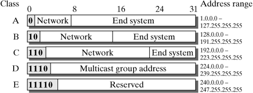
This addressing scheme was originally designed by assuming that each physical network could actually have a network identifier from one of the three classes mentioned above (depending on the size of the physical network). However, it was soon observed that this approach would quickly exhaust all available network prefixes. In addition, the existing classes proved often to be inappropriate: A class-A network could contain almost 224 or 16777216 end systems, a number that even the largest organizations would hardly need, apart from the fact that no known physical network technology can handle that number of end systems. In contrast, class-C networks are much more numerous, but cannot hold more than 254 end systems, which is not enough in many cases. These limitations motivated the development of technologies to better utilize the existing address space. The basic idea was to have the boundary between the network prefix and the end-system identifier at an arbitrary bit position, instead of only at the three positions dictated by the A, B, and C address classes. For example, a class-A network can be divided in two networks with half the size each by using the first bit of the end-system identifier for division: All end systems with a zero at this position fall into one network, and all systems with a one fall into the other network. This means that the network prefix has become longer by one bit inside of the new subnetworks, from the end systems' view. This new division of addresses is totally transparent to the outside; it plays no role for routing outside the networks directly concerned: Only the router that connects the two new networks to the rest of the world has to know and consider this new division. This scheme basically allows us to divide an address space several times. The length of the valid network prefix grows then in line with the depth of the hierarchy formed by this scheme. Similarly, when working in the opposite direction, we could group a block of class-C addresses into a larger address space for example, if they belong to a single organization (e.g., an Internet Service Provider). This corresponds to shortening the network prefix, forming a larger address space, which can be divided again, if necessary. In this case, it is not necessarily meaningful to have the new division transparent to the outside, because it would require many unnecessary routing entries. For example, if an organization had a block of 256 class-C addresses instead of one single class-B address, then 256 routing entries instead of a single one would have to be published globally.
Today, the Internet uses Classless Inter-Domain Routing (CIDR) [ReLi93, FLYV93], which virtually ignores the "old" class division of IP addresses: Network prefixes can have an arbitrary length. However, the information about the actual length of the network identifier of a specific network can no longer be seen from the first address bits, in contrast with the method seen in the classful scheme. Consequently, this information has to be passed on and stored with each network address. There are two common notations: In the first notation, the number of bits belonging to the network prefix is denoted in decimal form, with a slash separating it from the address. For example, 192.168.152.0/21 denotes a network with its prefix consisting of the first 21 bits of the IP address 192.168.152.0. The second notation denotes a bit mask in addition to the IP address; the bit mask has the same length as the IP address. It is called a network mask and has all bits corresponding to the positions of the network prefix in the IP address set to one. The network mentioned above would look as follows in this notation: 192.168.152.0/255.255.248.0.
Router Addresses Routers have their own IP addresses, as do all network nodes in TCP/IP networks. Because an IP address also identifies the network it belongs to, as we know from the previous sections, and because a router has to be connected to more than one network to be able to mediate between networks, it is obvious that a router has more than one IP address. More precisely, each network interface in a router has its own IP address. Figure 16-4 shows the sample networks from Figure 16-2 again to illustrate this concept, denoting IP addresses for all end systems and all network interfaces of each router. Figure 16-4. Assigning IP addresses to end systems and network interfaces in routers (example). 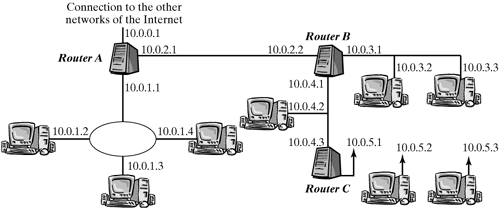
16.1.4 Forwarding Procedure For a router, an IP packet received over a network interface falls into one of three categories, depending on its destination address: The packet is addressed to the router: In this case, the packet is not forwarded, but passed to a protocol instance of the transport layer in the router. The packet is addressed to an end system in a neighboring network: Packets addressed to an end system in a network that is connected directly to the router over a network interface can be forwarded directly to this end system. When the packet is passed to the data-link layer, the physical address of the destination system, which might previously have been discovered by the ARP protocol, is used. The packet is addressed to an end system in a remote network: If the destination system is not in a neighboring network, then the packet has to be forwarded over an additional router. This router is identified from the forwarding information, and its physical address is used as destination towards the physical layer.
The first case is characterized by the fact that the IP destination address belongs to an internal network interface. The second case can be detected by AND-combining the destination address with the network masks of neighboring networks. If the result of this operation matches the network prefix of the respective network, then the destination system is in this network. The third case applies when none of the two previous conditions is true. In practice, the second case can be conveniently convered by the mechanism used to identify the next router in the third case, and "rule-based routing" is implemented in the recent kernel versions of Linux, so that the first case is also handled in this way. (See Section 16.1.6.) The exact procedure involved in identifying the next router for the third case is strongly linked to the data structure used to store the forwarding information in the router. This data structure will be discussed in the next section. Routing Table The structure of forwarding information can be thought of as a table, where each row describes a specific address range, which is defined by a network prefix. This routing table specifies the network interface or the next router to be used for forwarding of packets having their destinations in the specified address range. Figure 16-5 uses an example to show what a routing table for router B from Figure 16-4 could look like. We use designations common in Linux to name network interfaces. In practice, routing tables often include additional information in each row (e.g., describing the quality or the cost of a path, which help in selecting one of several routes to the same destination). Figure 16-5. Simple routing table for router B in Figure 16-4.Destination | Network Mask | Router | Interface |
|---|
10.0.3.0 | 255.255.255.0 | ?/P> | eth0 | 10.0.4.0 | 255.255.255.0 | ?/P> | eth1 | 10.0.5.0 | 255.255.255.0 | 10.0.4.3 | eth1 | 10.0.2.0 | 255.255.255.0 | ?/P> | ppp0 | 0.0.0.0 | 0.0.0.0 | 10.0.2.1 | ppp0 |
The example shows clearly how the second and third cases from the previous section can be distinguished: If the routing table includes an entry for a next router, then the packet has to be forwarded to that router. Otherwise, it can be sent over the specified network interface directly to the destination system. An entry in a routing table is also called a route in the following discussion, to simplify matters. Longest Prefix Denoting a network address and a network mask means that the network prefixes entered in a routing table can have an arbitrary length. They don't even have to describe a single network that actually exists, but can instead group several networks in neighboring address spaces to reduce the size of the routing table. The most extreme example for this is an entry having its prefix length zero or its network mask 0.0.0.0. Such an entry represents all destination networks and is actually valid. It supplies a default route the route packets should take when no specific entry exists for their destination address. Naturally, a clear regulation has to be found for conflicting cases where several matching prefixes exist for one destination address. For example, such a conflict happens when the routing table includes a default route and additional entries. The problem is solved by selecting the entry with the longest prefix from all entries with matching prefixes. This means that more specific information in the routing table has priority over less specific information. 16.1.5 Routing Cache The search for an entry with the longest matching prefix is the most time-critical operation in the forwarding procedure: It is used frequently, so its implementation should be efficient. In Linux, all routing-table entries are sorted by prefix length, and the table is searched successively by descending prefix length. This method is not always efficient, especially when the table includes many different prefixes. Rather than using different data structures to speed up the search process, Linux uses a routing cache to reduce the number of search processes. This cache stores the table entries used last and uses a hashing method that operates on the source address and destination address of packets to be forwarded, for accessing entries very fast. The routing table has to be consulted only for new address combinations not yet stored in the routing cache. This method represents a good solution for end systems with a relatively limited number of concurrent communication partners; it is probably less suitable in the core area of the Internet. 16.1.6 Rule-based Routing One routing particularity in Linux Version 2.4 and higher is that it lets you use several routing tables, instead of a single one. An additional set of rules is then used to select which table should be used for what packets. This method is called rule-based routing or policy routing and allows you to include other criteria (e.g., the source address) in the routing decision, in addition to the destination address, whereas routing decisions taken from one single routing table are always based only on the destination address and the destination-network prefix specified in that one table. Rules Each rule has a selector and a type. The selector chooses the packets to which the rule can be applied, and the type determines what should happen with a packet when the selector matches (e.g., that a specific routing table should be used or that a packet should be dropped). These rules are applied by priority values in ascending order. A unique priority value has to be assigned to each rule when it is defined. If a suitable route is found based on a rule, then the process is aborted, and the packet is forwarded. Otherwise, the process continues with the next rule. The selector can contain the source address, the destination address, and the network interface at which the packet to be forwarded arrived. In addition, you can use the TOS field (which has more recently been called codepoint see Section 14.1.2) or the iptables marking (see Section 19.3.5), which is called fwmark in the following discussion. Indirectly, the latter option lets you use additional packet properties (e.g., transport-protocol ports) for selection. All fields not explicitly stated in the selector are always considered to match. There are five types of rules: unicast, blackhole, unreachable, prohibit, and nat. The "normal case" is the unicast type: A specific routing table stated in the rule is searched for a route. The blackhole, unreachable, and prohibit types cause the packet to be discarded when the rule is applied. They differ only in the type of feedback to the sender: blackhole creates no feedback, unreachable reports that the destination network is unreachable, and prohibit reports that the communication is not permitted. The last rule type, nat, can be used for static network-address translation (NAT). It is designed for special routing applications and not for the purpose of using one single IP address for several computers. This mechanism would be unsuitable for this purpose, because it is stateless. We will see in Chapter 21 that the masquerading mechanism of iptables is suitable for such cases. The nat routing rules are discussed in more detail in the work of Alexey Kuznetsov [Kuzn99]. Default Settings By default, the Linux kernel specifies three rules of the unicast type, with a selector each matching all packets. The priorities and identifiers for routing tables used for each type are defined as follows: Priority | Table Name | Table Number | 0 | local | 255 | 32766 | main | 254 | 32767 | default | 253 |
The three routing tables, local, main, and default, which are searched according to the above rules in this order for matching routes, are also created automatically. The latter two are initially empty, and the system administrator has to add entries (or use suitable scripts to fill them with entries) when the system boots. The main table is intended for "normal" routing entries; the default table is suitable for lower-priority backup solutions. The rules belonging to the main and default tables can also be deleted or modified. In contrast to the second and third rules, the first rule is fixed, and the associated routing table is managed by the kernel itself. This table includes entries describing the addresses of local network interfaces. This realizes a very elegant approach to the categorizing of incoming packets, which was mentioned at the beginning of Section 16.1.4: Using just one procedure for all incoming packets, consult the set of rules and then the associated routing tables for each packet; if an entry is found in the local table, the packet is delivered locally otherwise, it has to be forwarded. Notice that only two tables, local and main, are searched in this order when rule-based routing is disabled in the kernel configuration. |