2.5 Clustered configuration
|
| < Day Day Up > |
|
From the benefits and functions discussed so far, it should be apparent that clustered configurations provide a great growth or scalability potential compared to traditional systems.
Clustered configurations are ideal for systems that have growth potential; adding nodes to an existing configuration is transparent to the application system or users.[2] It should be noted that when a computer is added within a clustered configuration, the system does not have to be shut down. After addition of a node to the configuration, the computer through its cluster manager immediately makes it cluster aware and is made available for access. The load is distributed from each of the existing nodes to the new node that joined the cluster.
Clustered configurations, apart from direct link address to one or more nodes, provide a single node link address called a cluster alias.[3] A cluster alias is one common address, or identification, given to all the nodes participating in the clustered configuration. It frees clients from having to connect to a specific cluster member for services. Similar to a host, clients can request a variety of services from a cluster alias. The cluster alias acts as a load balancer at the operating system level, monitoring resource availability on the various nodes participating in the clustered configura tion and directing new processes to the nodes that have a lower load. These built-in features, available at the clustered configuration level, give applications a great opportunity to perform and scale with minimum effort. This performance and scaling can be done while maintaining high availability of the systems as a whole.
While cluster aliases provide the load balancing capability within the nodes participating in the clustered configuration, the communications or requests that one node needs to make to other nodes participating in the cluster happens through another important component called the cluster interconnect.
2.5.1 Cluster interconnects
Nodes in a clustered configuration exchange information with each other by means of physical communication links known as interconnects. There are a variety of interconnecting options available with choices depending on the information exchange requirements of the applications running in the environment.
While interconnects provide a great deal of functionality by com municating across nodes in a clustered configuration, the basic strengths of an interconnect should be in the following areas:
-
Throughput: The throughput of an interconnect is a vital parameter for the performance of the clustered configuration while communicat ing between the nodes. When considering throughput, the measure ment is based on the average and maximum cumulative data transfer rates between nodes during processing of requests across nodes.
-
Availability: Availability of the application is also a very important requirement for systems that require a clustered configuration. Data transfer between the nodes in the cluster take place via these cluster interconnects; a failure at this level will cause disruption of service between the nodes and will affect the proper functioning of the application. Thus, redundant level interconnects should be provided to ensure continued uptime of the cluster interconnects.
-
Distribution: A functionality of the interconnect that complements the availability requirement is the support for distributed computing configurations. Because of this, the nodes in the clustered configuration do not have to reside in a small complex of buildings and may be spread throughout or across buildings.
Figure 2.9 represents a cluster interconnect. Nodes in the clustered configuration exchange information with each other by means of physical communication links. The interconnect provides a great deal of functionality by helping communication across nodes in the cluster. There are various kinds of interconnects available and based on the type of hardware systems used, any of the interconnects may be used. In order to obtain an appropriate introduction to the various interconnects available, a brief overview for the following interconnects is provided:
-
Computer interconnect (CI)
-
Local area network interconnects (LAN)
-
Gigabit Ethernet interconnects
-
InfiniBand
-
Virtual interface architecture
-
Hyper messaging protocol
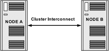
Figure 2.9: Cluster inter connect.
Computer interconnect
Computer interconnect (CI) is an early version of the interconnect. VAXClusters used this kind of interconnect with Version 4.0 of VMS. The CI supports the exchange of information at the rate of 70 megabits per second. Data is physically sent to the CI one bit at a time, which makes the CI a serial interconnect. Data is sent as one or more packets with each packet containing at least 7 bytes of information.
The CI provides a dual path access with two distinct signal paths, path A and path B, which are used for communicating among its nodes. These paths are implemented such that none of their components is a potential single point of failure. The CI has high-availability characteristics. Each path in the interconnect has the capacity to transfer data at 70 megabit per second ''per path.'' For example, in a four-node clustered configuration, one node can send data to a second node at 70 megabits per second on path A, while a third node concurrently sends data to a fourth node at 70 megabits per second on path B.
CI is a multidrop interconnect (i.e., each packet transmitted on a CI can be seen by every CI port adapter attached to that CI). Each packet identifies a CI adapter on the node to which the packet is being sent and only the adapter actually accepts the packet from the interconnect.
When a packet is being transmitted, the configuration module reads data out of the main memory as 32-bit longwords and passes them to the data path (DP) module. The DP module breaks the 32-bit longword down into 8 bit bytes. These bytes are then passed to a packet buffer (PB) module where they are placed in a hardware transmit buffer. Once the entire packet is assembled on the PB module, the data link (LINK) module acquires one path on the CI and then transmits the data in serial format one bit at a time.
Figure 2.10 represents nodes connected together, or communicating with each other, through the CI. The network connections are made directly to the adapters on each cluster member, which in turn is connected to the network line.
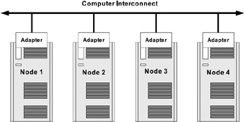
Figure 2.10: Computer interconnect representation.
When a packet is being received, the LINK module accepts the data in serial format from one path of the CI. The LINK module converts the data into byte format and deposits each byte into the hardware receive buffer on the PB module. Once the entire packet has been received, the data is then fetched as bytes from the hardware receive buffer, moved across the DP module where it is assembled into 32-bit longword and then handed to the configuration module. The configuration module then writes the data into a buffer in the main memory of the node to which the adapter is attached.
Local area network interconnects
The CI discussed above is used to communicate between nodes that reside in a relatively small geographic area. However, nodes that use a traditional network interconnect, such as the Ethernet and the Fiber Distributed Data Interface (FDDI), to communicate with each other can be distributed over a much larger geographical area.
Ethernet has been in existence for almost 25 years now and has progressed along with networking requirements. Invented by Dr. Robert Metcalf and pioneered by Digital and Xerox, Ethernet has become one of the most commonly used LAN technologies worldwide.
As a transport protocol, Ethernet operates at Layers 1 and 2 of the 7-layer Open Source Initiative (OSI) networking model, delivering its data packets to any device connected to the network cable.
Another local area network interface that is quite popular for transfer of packets of information between computers or technical devices is the Fiber Distributed Data Interface (FDDI). FDDI is a fiber optic serial bus that provides for the exchange of information at the rate of 100 megabits per second. FDDI is defined by American National Standard Institute (ANSI) and OSI standards and was originally designed to operate over fiber optic cabling. However, it also includes standard copper media for interconnection. FDDI uses a token ring media access control protocol. A token consists of a special three-octet FDDI frame. A station waits until a token comes by, grabs the token, transmits one or more frames, and releases the token.
Both Ethernet and FDDI are known as local area network (LAN) interconnects. Ethernet is commonly used to support communication among several offices, throughout a building or among several buildings in close proximity to each other. A common application of Ethernet is the networking of computers throughout an automobile assembly plant or a business establishment. FDDI also has a similar use, but it often supports communication over greater distances than Ethernet.
FDDI and Ethernet can coexist on a single network configuration. For example, Ethernet can be used to link together nodes on two sites; FDDI can then be used to link the two sites together into a single network. If computers are distributed across buildings, they could be placed inside an FDDI ring, allowing them to exist as a single configuration. This enables faster data communication between computers in the buildings.
Ethernet is a single-path, multidrop serial bus that supports the exchange of information at the rate of 10 megabits per second or more. A number of different types of wire and fiber optic cable can serve as the physical media within an Ethernet LAN. Specific limitations on cable lengths and distances vary with the media used. While Ethernet has evolved over the years, there are Ethernets that started at 10 megabits per second and have increased to 100 megabits per second. Currently there are Ethernets that support exchange of information at 1000 megabits (1 gigabit) per second.
Gigabit Ethernet interconnects
Gigabit Ethernet has evolved from the original 10 Mbps Ethernet standard, 10 BASE-T and the 100 Mbps Fast Ethernet standards, 100 BASE-TX and 100 BASE-FX. The IEEE and the 10-Gigabit Ethernet Alliance support a 10 Gbps Ethernet standard. Gigabit Ethernet is the latest evolution of networking options providing excellent high-speed communication between devices.
In 1998, IEEE adopted a standard for Gigabit Ethernet over fiber optic cabling and subsequently, in 1999, adopted Gigabit Ethernet over copper as 1000BASE-T. This allowed gigabit speeds to be transmitted over Cat-5 cable. Figure 2.11 represents the two IEEE standards adopted for Gigabit Ethernet over fiber optic cabling and copper.
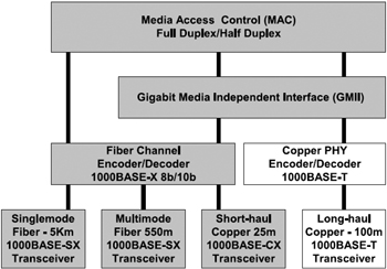
Figure 2.11: Gigabit Ethernet standards. (Source: Gigabit Alliance).
Benefits of using Gigabit Ethernet over its predecessors, or over fiber optics includes the following:
-
Gigabit Ethernet is 100 times faster than regular 10 Mbps Ethernet and 10 times faster than 100 Mbps Fast Ethernet
-
Increased bandwidth for higher performance and elimination of bottlenecks
-
Full-duplex capacity allowing for the virtual doubling of the effective bandwidth
-
Full compatibility with the large installed base of Ethernet and Fast Ethernet nodes
-
Transfer of large amounts of data across network quickly
Ethernet network solutions are used in all major industries where the requirement for high-speed reliable communication is a necessity. Many of these segments continue to use the earlier version of the Ethernet. Due to the high performance benefits with Gigabit Ethernet over the traditional Fast Ethernet, the new Gigabit Ethernet solutions will replace the existing ones in a short to medium time frame.
Table 2.2 illustrates the bandwidth requirements in the various sectors of the information technology arena within the various implementation zones like data warehousing, office automation, online transaction processing systems (OLTP), etc. This details the data transfer sizes and the networking needs to meet these requirements.
| Application | Data Types/Size | Network Traffic Implication | Network Need |
|---|---|---|---|
| Scientific modeling, engineering |
|
|
|
| Publications, medical data transfer |
|
|
|
| Internet/ Intranet |
|
|
|
| Data warehousing, network backup |
|
|
|
| Desktop video conferencing, interactive whiteboarding |
|
|
|
|
[a]Source: "Gigabit Ethernet accelerating the standard for speed," Gigabit Ethernet Alliance, http://www.10gea.org/Tech-whitepapers.htm | |||
Every network connection has two points: an origin and a destination. The origin is the point where the data/message is sent from and the destination is the point to where the data/message is being sent. Data/ messages are transmitted between the two points, and are transferred in packets of information. In an Ethernet connection, the size and packet frame is defined by the IEEE 802.3 specification. (The packet format/frame has not changed between the fast Ethernet and Gigabit Ethernet.)
Figure 2.12 provides a dissection of the Ethernet packet as defined by the IEEE 802.3 specification. This dissection shows the total length of the packet that contains the source, the destination address, and the actual message. While a certain portion of the packet is of a fixed length, the remaining portion that contains the actual message, or data, is of a variable length between 0 and 1500 bytes (i.e., a maximum frame size of 1524 bytes). As indicated above, there has been no change in the frame specification between Fast Ethernet and Gigabit Ethernet; however, the speed of transmitting these packets has increased by a magnitude. This makes it a favorable choice for high-speed data transfer in a data processing environment. It is to be noted that, in most scenarios, there is a tendency for most systems to show a degraded result. In the case of a Gigabit Ethernet connection with an increased load, this was not noticed. A recently performed test by the Gigabit Ethernet Alliance group noted a high linear scalability measurement at various packet sizes. Both the theoretical throughput and actual throughput, in all the various packet sizes, produced the same performance results.
![]()
Figure 2.12: IEEE 802.3 frame specification.
Figure 2.13 represents the Gigabit Ethernet performance at various packet sizes. It should be noted that the performance measurement is linear with increase in packet size.
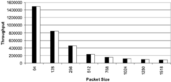
Figure 2.13: Gigabit Ethernet perfor mance chart.
In a clustered configuration, Gigabit Ethernet plays an important role by providing a higher bandwidth over the traditional Fast Ethernet.
While the Gigabit Ethernet connections are becoming popular, the networking research has not ended. Recently, another technology called InfiniBandTM has started to evolve. While Ethernet, fiber channel, and ultra SCSI are the current popular interconnect methods deployed at various locations, InfiniBand technology is becoming popular. InfiniBand technology will be discussed in the following section.
InfiniBand technology
The demands of the Internet and distributed computing are challenging the scalability, reliability, availability, and performance of servers. InfiniBand architecture represents a new approach to I/O technology and is based on the collective research, knowledge, and experience of the industry's leaders and computer vendors. The main developmental goal for this collaborative effort is to establish one standard method of high-speed communication from amongst the many that are currently available.
The evolution of the InfiniBand architecture springs from two competing standards: Next Generation I/O (NGIO) and Future I/O. Through the efforts of key marketing strategies, both standards converged in mid-1999 to form InfiniBand. It is currently represented by Sun Microsystems, Compaq, Intel, Microsoft, IBM, Hewlett-Packard, and Dell, and 140 other organizations have joined as a collective effort.
InfiniBand architecture specifies channels that are created by attaching host channel adapters within a server chassis to host channel adapters in other server chassis. This is done for high-performance interprocess communication (IPC) and to target channel adapters connecting InfiniBand-enabled servers to remote storage and communication networks through InfiniBand switches. InfiniBand links transfer data at 2.5 Gbps, utilizing both copper wire and fiber optics for transmission. It can carry any combination of I/O, network, and IPC messages.
InfiniBand architecture (Figure 2.14) has the following communication characteristics:
-
User level access to message passing
-
Remote direct memory access (RDMA) read and write
-
Up to a maximum of 2 GB message in a single transfer
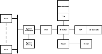
Figure 2.14: InfiniBand architecture.
The memory protection mechanism defined by the InfiniBand architecture allows an InfiniBand host channel adapter (HCA) to transfer data directly into or out of an application buffer. To protect these buffers from unauthorized access, a process called memory registration is employed. Memory registration allows data transfers to be initiated directly from user mode, eliminating a costly context switch to the kernel. Another benefit of allowing the InfiniBand HCA to transfer data directly into or out of application buffers is that it can remove the need for system buffering. This eliminates the context switch to the kernel, and also eliminates the need to copy data to or from system buffers on a send or receive operation respectively.
InfiniBand architecture also has another unique feature called a memory window. The memory window provides a way for the application to grant remote read and/or write to a specified buffer at a byte-level granularity level to another application. Memory windows are used in conjunction with RDMA read or RDMA write to control remote access to the application buffers. Data can be transferred either by the push or pull method (i.e., either the sending node would send the data over to the requester which is called pushing or the requester could get to the holder and get the data, which is called pulling).
While InfiniBand has just begun, it promises tremendous potential and benefits in a clustered configuration where transfer of data is required to happen via the cluster interconnect.
Virtual interface architecture
The virtual interface (VI) architecture, authored and developed by Compaq (now HP), Intel, and Microsoft, is designed for hardware and software vendors and provides adapters, switches, middleware, and end-user application software that will seamlessly grow as servers or workstations are added and integrated into a clustered system area network (SAN). A SAN relies on high-speed, reliable messaging without the traditional communications protocol overhead as experienced by current LAN or WAN adapters and protocols, such as Ethernet, token ring, fiber channel standard, systems network architecture (SNA), or even asynchronous transfer mode (ATM).
The VI architecture is to be used where server-to-server messages deal with application and data availability, and it allows any server error or failure to cause an immediate transfer of the business critical application to another server for uninterrupted processing. The architecture also allows for parallel application processing and minimizes performance bottlenecks where more traditional communications protocols such as the Remote Procedure Call (RPC), User Datagram Protocol (UDP), and sockets have caused application processing delays due to protocol stack handling and/or network traffic overloads due to collision detection processing. These slowdowns cause application delays or inefficient use of the cluster.
Figure 2.15 illustrates the VI-architecture-based cluster interconnect architecture. That provides high-speed interconnect between Intel-based severs.
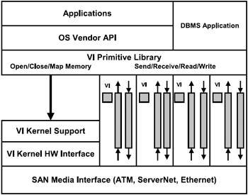
Figure 2.15: Virtual interface architecture.
VI architecture implementations will consist of three components: SAN media which will be equipped with VI architecture registers and memory, the VI architecture primitive library (VIPL) which will support application use of the architecture, and the VI architecture operating system kernel support services.
Hyper Messaging Protocol (HMP)
Hewlett-Packard (HP), in cooperation with Oracle, has designed a cluster interconnect product specifically tailored to meet the needs of enterprise class parallel database applications. HP's Hyper Messaging Protocol (HMP) significantly expands on the feature set provided by TCP/UDP by providing a true reliable datagram model for both RDMA and traditional message semantics. Coupled with operating system bypass capability and the hardware support for protocol offload provided by HyperFabric, HMP provides high bandwidth, low latency and extremely low CPU utilization with an interface and feature set optimized for business critical parallel applications such as Oracle 9i RAC.
[2]COMPAQ Tru64 Unix Version 5.1 and above when the clustering version is installed.
[3]COMPAQ Tru64 Unix Version 5.1 and above when the clustering version is installed.
|
| < Day Day Up > |
|
EAN: 2147483647
Pages: 174