Pixel Shaders for Video Image Manipulation
Vertex and pixel shaders are currently one of the most exciting areas in 3-D graphics. Although shaders are generally used for advanced lighting effects, pixel shaders can also be used for image processing, which opens up some interesting possibilities in the world of video. The Pixellator sample located in the AVBook\bin directory demonstrates just a few of these possibilities (see Plate 10).
| |
A pixel shader is a program that runs on the graphics processing unit (GPU). For every pixel that is drawn, the pixel shader receives the interpolated texture, diffuse color, and specular color values as input, and produces the final pixel color as output. The pixel shader is invoked once for every pixel that is drawn (including overdraw) on every rendering pass, so they need to be quite small ” generally, anywhere from a few to a dozen lines of code, written in a strange form of assembly language. (High-level shading languages are the next logical step. They were introduced in DirectX 9, but are still something of a moving target. By the time you read this book, writing shaders in assembly language may be completely pass .)
An excellent resource for learning about vertex and pixel shaders is Direct3D Shader X , by Wolfgang F. Engel, ed. The chapter Image Processing with 1.4 Pixel Shaders in Direct3D, by Jason L. Mitchell, is particularly relevant for video, although he describes processing still images. Another recent book is Microsoft DirectX 9 Programmable Graphics Pipeline , by Kris Gray (Microsoft Press).
| |
Loading the Shader
Loading a pixel shader into memory is straightforward. First, check to make sure that the video adapter supports the required pixel shader version. Versions 1.1, 1.2, and 1.3 are closely related , while the instruction set in version 1.4 is much different than the other versions. (At the time that this book went to press, Nvidia drivers support 1.3 and ATI drivers support 1.4.) Here is a small helper function that checks the shader version.
// Queries whether the desired pixel shader version is supported. HRESULT QueryPixelShaderVersion( IDirect3DDevice9 *pDevice, DWORD major, DWORD minor) { if (!pDevice) { return E_POINTER; } D3DCAPS9 caps; pDevice->GetDeviceCaps(&caps); if (caps.PixelShaderVersion < D3DPS_VERSION(major, minor)) { return E_FAIL; } return S_OK; } Assuming that the video adapter supports the required version, you can assemble the shader code from a text file by calling the D3DXAssembleShaderFromFile function, which is part of the DirectX extensions library.
CComPtr<ID3DXBuffer> pCode; CComPtr<ID3DXBuffer> pErrorMessages; hr = D3DXAssembleShaderFromFile(szFileName, 0, NULL, 0, &pCode, &pErrorMessages); if (FAILED(hr)) { OutputDebugString((TCHAR*)pErrorMessages->GetBufferPointer()); return hr; } If the method succeeds, the pCode variable points to a buffer that contains the assembled code. If the method fails, pErrorMessages points to a buffer that contains an error message. (Instead of loading from a text file, you can also store the shader code in memory or in a resource file. If so, use the D3DXAssembleShader or D3DXAssembleShaderFromResource function, respectively.) Next if the assembly step was successful, create the pixel shader by calling IDirect3DDevice9::CreatePixelShader . Activate the pixel shader by calling IDirect3DDevice9::SetPixelShader .
// Get a pointer to the buffer that contains the assembled shader code. DWORD *pFunction = (DWORD*)pCode->GetBufferPointer(); // Create the shader. CComPtr<IDirect3DPixelShader9> m_pShader; hr = m_pDevice->CreatePixelShader(pFunction, &m_pShader); if (SUCCEEDED(hr)) { // Make the shader active. hr = m_pDevice->SetPixelShader(m_pShader); m_effect = iShader; } Grayscale Shader
Here is a simple shader that converts a color image to grayscale. (See Plate 11.) The idea is to multiply each RGB component by a scaling factor, sum the result to produce a luminance value, and replicate this value in all three color channels.
ps_1_1 def c0, 0.299, 0.587, 0.114, 1.0 tex t0 dp3 r0, t0, c0
The ps statement declares the required version number ” in this case, 1.1. The def statement declares a set of scaling constants for the RGB components . (Each shader register contains four float values, so you can place all three scaling factors into one register.) The tex statement reads the color from the current texture into the t0 register. The dp3 statement performs a dot product operation on the first three float values stored in registers t0 and c0, and places the result in r0. In other words, the dp3 statement calculates the following sum, where .b , .r, and .g are the red, green, and blue values in each register:
(c0.r — t0.r) + (c0.g — t0.g) + (c0.b — t0.b)
The final pixel color is always placed in the r0 register. When the pixel shader finishes executing, r0 must contain the color information for the pixel.
Sepia Tone Shader
In Direct3D ShaderX , Mitchell presents a technique for converting a color image to sepia tone, using a version 1.4 pixel shader. You can also achieve the same effect with a version 1.3 pixel shader. It requires a bit more work by the application, but the principle is the same. Each pixel is converted to grayscale, and the grayscale value is used to look up a color in a one-dimensional texture that holds the sepia tones. (See Figure 11.5.)
The process of looking up a texture value from a calculated result is called a dependent read. Version 1.4 of the pixel shader language supports dependent reads from color registers, but this capability is not available in version 1.3. Instead, we can use the texdp3tex instruction. This instruction calculates the dot product between a texture coordinate and a texture color value, and uses the result to perform a 1-D texture lookup. In other words, it calculates the following sum, where (x, y, z) is a texture coordinate value and (r, g, b) is a texture color value:
(x — r) + (y — g) + (z — b)
The texdp3tex instruction uses the resulting value to look up a color in a 1-D texture. Thus, we can convert the texture color to grayscale by placing the scaling factors (0.299, 0.587, 0.114) in the texture coordinates. Here is the pixel shader.
ps.1.3 tex t0 texdp3tex t1, t0 mov r0, t1
The dot product is applied to the color value in texture stage 0 (the t0 register) and the texture coordinates in stage 1 (the t1 register). The 1-D lookup is performed on the stage 1 texture, and the result is placed in the t1 register.
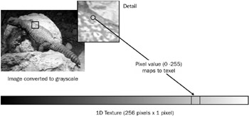
Figure 11.5: Dependent read for sepia tone shader.
In the application, we need to set up the texture stages correctly to match the shader.
// Define the grayscale weights. float luma_red = 0.299f, luma_green = 0.587f, luma_blue = 0.114f; // Define the vertex format. const DWORD VERTEX_FORMAT = D3DFVF_XYZRHW D3DFVF_TEX2 D3DFVF_TEXCOORDSIZE3(1); // Note: D3DFVF_TEXCOORDSIZE3(1) means texture coordinate set 1 has // three values (u,v,w) instead of two, which is the default. struct VERTEX { float x, y, z, rhw; // Vertex coordinates, in screen space (video). float tu, tv; // Texture 0 (video). float tu2, tv2, tw2; // Texture 1 (grayscale conversion weights). }; // Define the vertices. VERTEX vertices[] = { // x y z rhw tu tv tu2 tv2 tv3 { 0.0f, 0.0f, 0.5f, 1.0f, 0.0f, 0.0f, luma_red, luma_green, luma_blue}, { fWidth, 0.0f, 0.5f, 1.0f, fTU, 0.0f, luma_red, luma_green, luma_blue}, { fWidth, fHeight, 0.5f, 1.0f, fTU, fTV, luma_red, luma_green, luma_blue}, { 0.0f, fHeight, 0.5f, 1.0f, 0.0f, fTV, luma_red, luma_green, luma_blue} }; m_pDevice->SetTexture(0, pVideoTexture); m_pDevice->SetTexture(1, m_pSepiaTexture); m_pDevice->SetTextureStageState(1, D3DTSS_TEXCOORDINDEX, 1); m_pDevice->SetTextureStageState(1, D3DTSS_TEXTURETRANSFORMFLAGS, D3DTTFF_COUNT3); The tu2 texture coordinates are the same grayscale weights that we used in the previous shader. The dot product is simply an intermediate value, which is then used to look up a color value in the 1-D sepia tone texture. The stage 1 texture coordinates, therefore, are not really used as coordinates ” they are just a place to store data.
You re not limited to a sepia tone with this shader. The grue effect in the Pixellator sample uses the same pixel shader, but maps the grayscale values to different shades of gr een and bl ue . (See Plate 12.)
Fuzzy Dots
Sepia tone is an interesting effect, but you can create even crazier effects with pixel shaders. We created one for the Pixellator sample that we call fuzzy dots (see Plate 12). Like the sepia tone shader, the fuzzy dots shader performs a dependent read to look up a texture value, but it uses a three-dimensional (volumetric) texture instead of a 1-D texture.
We used the DirectX Texture tool to create a 64 — 64 — 8 volumetric texture. Each layer of the texture consists of randomly placed red, green, and blue dots, whose density progressively decreases with each layer. The pixel shader maps the 64 — 64 bitmap to the render target, using texture coordinates that range from 0 to 8.0 horizontally and 0 to 4.0 vertically. The texture addressing mode is set to D3DTADDRESS_WRAP , so the bitmap is tiled 32 times. The color value for each pixel is then determined by using the grayscale value to perform a dependent read along the z-axis of the texture. Because the density of dots decreases at each layer, the dot density across the rendered image roughly corresponds to the grayscale value of the original image. (See Plate 13.)
Incidentally, we used GDI+ to generate the eight bitmaps for the texture. If your only experience till now has been with the old GDI, you should definitely check out GDI+, because it makes simple drawing applications like this one very easy.
The following shader program requires a 1.4 pixel shader.
ps.1.4 def c0, 0.30f, 0.59f, 0.11f, 1.0f texld r0, t0 texcrd r1.xyz, t1 dp3 r1.z, r0, c0 phase texld r1, r1 mov r0, r1
The first texld instruction loads the color value from video texture into register r0. The texcrd instruction loads the texture coordinates for the volumetric texture into register r1. The dp3 instruction performs a dot product between the color value in t0 and the grayscale weights in register c0. The result is placed only in the z component of register r1. The r1 register contains x- and y-coordinates that were specified by the application, and a z-coordinate that equals the grayscale value of the video image. Following the phase instruction, the second texld instruction performs a dependent read from the volumetric texture, using the texture coordinates in r1. (In 1.4 pixel shaders, the phase instruction permits the shader program to perform texture loads after performing arithmetic operations.) The resulting RGB value is then moved into r0, where it becomes the output pixel color.
EAN: 2147483647
Pages: 120