| Each function can have its own capability block, facilitating a mapping of interrupts to functions. The capability block not only defines the number of interrupts the function is designed to use, but also provides a way for system software to define the contents of the Interrupt Information fields that will be delivered to the host during each Interrupt Request. Interrupt Capability Block Format Figure 8-7 on page 210 illustrates the fields within the capability block and further illustrates the relationship between each interrupt supported and its associated Interrupt Definition Registers. Each field has the following purpose: -
Capability ID (08h) ” This field identifies this as an HT Capability Block -
Capability Type (80h) ” This field specifies the type of HT Capability Block as the Interrupt Discovery and Configuration Capability Block -
Capabilities Pointer ” Pointer to the next Capability Block -
Index ” The value selects the entry within the register stack to be accessed. -
Dataport ” Configuration transactions targeting this dataport permit access to the register selected by the index register value. Figure 8-7. Format of Interrupt Discovery and Configuration Capability Block 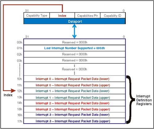 The index field of the Interrupt Discovery and Configuration Capability Block selects 32-bit entries within a register stack (or data structure) that defines the number of interrupts the function uses and includes a corresponding Interrupt Definition Register for each interrupt. Last Interrupt Supported Figure 8-7 on page 210 illustrates the Last Interrupt Supported register. This register is accessed through the dataport field of the capability block when selected with an index value of 01h. The register specifies the highest interrupt number used in conjunction with the function or ReqID. Interrupt numbers start at zero and are assigned sequentially. The example chosen in Figure 8-7 shows a value of 3 in the Last Interrupt Supported register, indicating there are 4 interrupts used by this function. Interrupt Definition Registers Each interrupt message specified for this function has a corresponding Interrupt Definition register (See Figure 8-7). These 64-bit registers are accessed 32-bits at a time via the Interrupt Discovery and Configuration Capability Block index field. The specification defines the relationships between the index and interrupt numbers as listed below: -
Index 10h points to bits [31:0] of Interrupt 0 Interrupt Definition register. -
Index 11h points to bits [63:32] of Interrupt 0 Interrupt Definition register. -
Index 12h points to bits [31:0] of Interrupt 1 Interrupt Definition register. -
Index 13h points to bits [63:32] of Interrupt 1 Interrupt Definition register. -
Index 14h points to bits [31:0] of Interrupt 2 Interrupt Definition register. -
Index 15h points to bits [63:32] of Interrupt 2 Interrupt Definition register. -
etc. Table 8-1 on page 212 defines the contents of the Interrupt Definition register. Table 8-1. Contents of the Interrupt Definition Registers | Bit | R/W | Reset | Description | | 63 | R/C | | Waiting for EOI ” This bit only has meaning if Request EOI (bit 5) is set (1). This bit is set by hardware when an interrupt request is sent and it is cleared when the corresponding EOI is returned. Software may also clear this bit by writing a 1 to it. | | 62 | R/W | | Pass PW ” This bit determines the state of the PassPW bit within the interrupt request packet. When set (1) no ordering of this message is guaranteed with respect to other upstream transactions. When cleared (0) ordering of this message is maintained within the posted channel. This bit may be read-only if single behavior is supported. | | 61:56 | R/O | | Reserved | | 55:32 | R/W | | IntrInfo[55:32] ” value is implementation specific. | | 31:24 | R/W | F8h | IntrInfo[31:24] ” This field is implemented as part of the interrupt address (Addr[31:24]). The default value is F8h for backward compatibility with 1.01 and earlier HT devices. The actual number of address bits used within a device is implementation specific. | | 23:6 | R/W | | IntrInfo[23:6] ” value is implementation specific. | | 5 | R/W | | IntrInfo[5] (Request EOI) ” This bit permits a device to request an EOI packet be sent after the interrupt service has completed. When set (1) the device waits for an EOI packet (by monitoring the "Waiting for EOI" bit to be cleared) before sending the next interrupt. | | 4:2 | R/W | | IntrInfo[4:2] Message Type ” value is implementation specific. See Chapter 22, entitled "X86 CPU Compatibility," on page 491 for an example use in x86 platforms. | | 1 | R/W | | Polarity ” Specifies the polarity of the interrupt trigger in HT devices with external interrupts (e.g. PCI bridge). 1=active low and 0=active high. | | | R/W | 1 | Mask ” When set (1) interrupt messages are not sent from this source. |  |