| HyperTransport bridges make use of the same HyperTransport Host/Primary and Slave/Secondary advanced capability blocks already defined for non-bridge devices. Non-bridge HyperTransport device configuration is described in Chapter 13, entitled "Device Configuration," on page 305. Second, they implement the type 1 configuration space header common to all PCI-compatible bridges (with the redefinition of certain bits described shortly). This is fortunate because: -
HyperTransport bridges maintain software compatibility with PCI bridges. -
Bridge headers already contain two sets of control/status registers for managing two independent interfaces, making support for mixed HyperTransport and PCI/PCI-X bridges a reasonable extension. Each set of primary/secondary bus registers is programmed (and interpreted) according to whether the specific interface is HyperTransport, PCI, or PCI-X. Same Slave/Primary And Host/Secondary Blocks The Slave/Primary and Host/Secondary capability blocks used in non-bridge devices such as tunnels and end (cave) devices are also used for the HyperTransport interfaces of bridges. Figure 16-1 on page 410 depicts a simple HyperTransport-to-HyperTransport bridge with a single secondary chain. Note that a bridge must implement a separate Host/Secondary interface block for each secondary bus it supports. Figure 16-1. HyperTransport-HyperTransport Bridge Interfaces 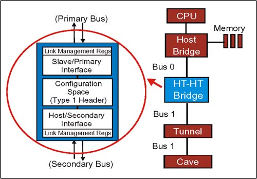 HyperTransport Bridge Header Fields In this section, the configuration space type 1 header format for HyperTransport bridge devices is described. For the most part, HyperTransport bridges use these fields in the same way as PCI bridges; the differences are described here. Header fields not mentioned are used in the same way as in PCI bridges. Refer to "The Type 0 Header Format" on page 322 for a description of HyperTransport non-bridge type 0 headers. Bridge Header Command Register Lower 16 bits at dword 01. The bridge header Command register is used by software to enable basic capabilities of the bridge on its primary bu s, including bus mastering, target address decoding, error responses, etc. Bits marked "0" in Figure 16-2 are not used (hardwired = 0); refer to Table 16-1 for bit definitions. Figure 16-2. HyperTransport Bridge Header Command Register 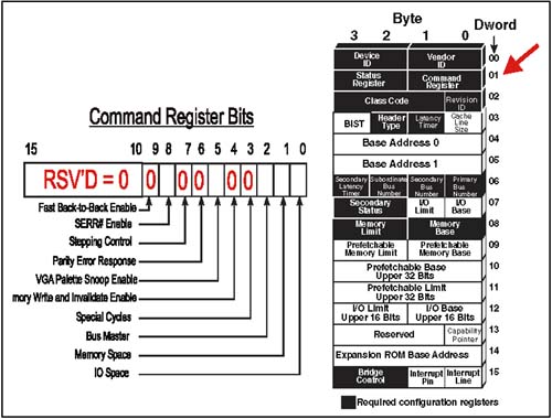 Table 16-1. HyperTransport Bridge Header Command Register Bit Fields | Bit | Function | | | I/O Space . When this bit is set to a one, the primary bus interface of the bridge may act as a target of requests in the I/O portion of the HyperTransport memory map. If this bridge is also a subtractive decoder, the setting of this bit does not affect the device's ability to claim requests with Compat bit set. Warm Reset to 0. | | 1 | Memory Space. When this bit is set to a one, the primary bus interface of the bridge may act as a target of requests in the Memory portion of the HyperTransport memory map. If this is a subtractive decoder, the setting of this bit does not affect bridge's ability to claim requests with Compat bit set. Warm Reset to 0. | | 2 | Bus Master . When set to a one, enables the bridge to forward transactions from the secondary interface to the primary interface. If cleared, the transaction will not be forwarded. If the secondary interface is PCI and targets the primary bus while this bit is clear, it will not be claimed by the bridge (result is master abort). If the secondary interface is HyperTransport, the bridge will set EOC error and issue an error response with NXA set (for non-posted requests).Warm Reset to 0. | | 5 | VGA Palette Snoop Enable . (Optional) if not implemented, tie bit = 0. If implemented and set, WrSized (byte) transactions originating on the primary bus targeting the lower 64KB of I/O address range (See System Memory Map) will have address bits 9:0 compared to 3C6h, 3C8h, 3C9h (VGA I/O registers). If there is a match the transaction will be forwarded to the secondary bus. If this bit is set, transactions originating on the secondary bus targeting these addresses will not be forwarded upstream. Note: if address remapping is in use, the address decoding of the bridge may be undefined when this bit is set = 1. | | 8 | SERR# Enable . When set to a one, the device will flood all outgoing links with sync packets in the event of an error which has been programmed to cause a sync flood. If this bit is clear, device only generates sync packets as a part of initial link synchronization. Bit does not affect device's ability to propagate sync flood packets from one link to another in a chain. Note: sync flood is similiar to SERR# assertion in PCI . Warm Reset to 0. | | Other Bits | All other bridge header Command Register bits are unused in HyperTransport bridges, and should be tied to a low level. | Bridge Header Status Register Upper 16 bits at dword 01. The HyperTransport bridge header Status register is implemented and used in the same manner as for non-bridges to report status on the primary bus. As in the case of the Command register, a number of these bits are used differently than in PCI, or not at all. Bits marked "0" in Figure 16-3 are not used (hardwired = 0); refer to Table 16-2 on page 414 for bit definitions. Figure 16-3. HyperTransport Bridge Header Status Register 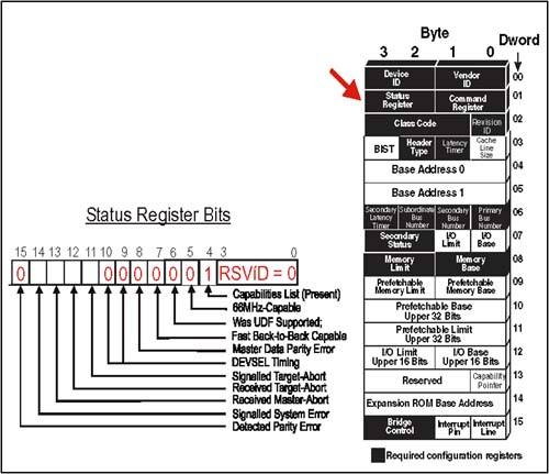 Table 16-2. HyperTransport Bridge Header Status Register Bit Fields | Bit | Function | | 4 | Capabilities List . (Introduced in the PCI 2.2 Specification) When this bit is hardcoded to a one, the device indicates there are one or more advanced capability block register sets to be discovered . All HyperTransport devices are required to have at least one advanced capability block (to support HyperTransport), so this bit is always set = 1. When software reads this bit high, it indicates that the Capabilities Pointer (at dword 13) is valid, and points to the first capability register set. | | 11 | Signalled Target Abort. This status bit indicates that a HyperTransport bridge, acting as a target on its primary interface, has aborted and generated a non-NXA error response to the requestor . Cold Reset = 0. | | 12 | Received Target Abort. This status bit indicates that a HyperTransport bridge, acting as a requester on its primary interface, has received a non-NXA error response to a request it issued. This is equivalent to the Target Abort event on PCI. Cold Reset = 0. | | 13 | Received Master Abort. This status bit indicates that a HyperTransport bridge, acting as a requester on its primary interface, has received an NXA (non-existent address) error response to a request it has issued. The NXA error response is returned by the end-of-chain device acting on behalf of the intended target. This is equivalent to the Master Abort event on PCI. Cold Reset = 0. | | 14 | Signalled System Error. This status bit indicates that a HyperTransport device has flooded the link with Sync packets (indicating a serious error). A device merely forwarding Sync packets from another device should not set this bit; this allows identification of the offending device(s). A link reset is required before accessing the device. Cold Reset = 0. | | Other Bits | All other bridge header Status Register bits are unused in HyperTransport, and should be tied to a low level. | Secondary Status Register Upper 16 bits at dword 07. If the secondary bus in the bridge is HyperTransport, many of the Secondary Status register bits used by PCI-PCI bridges are not used and tied to "0" as shown in Figure 16-4 on page 415; refer to Table 16-3 on page 416 for definitions of the active bits. Figure 16-4. HyperTransport Bridge Header Secondary Status Register 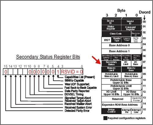 Table 16-3. HyperTransport Bridge Secondary Status Register Bit Fields | Bit | Function | | 11 | Signalled Target Abort. When set =1, this bit indicates that the bridge has issued a target abort on the secondary bus. If the secondary bus is HyperTransport, an error response with NXA set was sent because a request packet was received by the bridge in error. Cold Reset = 0. | | 12 | Received Target Abort. When set = 1, this bit indicates bridge received a target abort on the secondary bus. If the secondary bus is HyperTransport, the bridge received an error response with NXA set to one of its non-posted requests. Cold Reset = 0. | | 13 | Received Master Abort. When set = 1, this bit indicates the bridge had to abort a transaction request on the secondary bus. In HyperTransport, this means it sent a non-posted directed request which did not find the intended target, and the device at the end of the chain returned an error response with NXA set. Cold Reset = 0. | | 14 | Detected System Error. When set = 1, bridge detected a catastrophic error (SERR# in PCI) on the secondary bus. In HyperTransport, this bit indicates that a Sync flood was detected on the secondary bus. Cold Reset = 0. | | Other Bits | If the secondary bus is HyperTransport, all other Secondary Status register bits are unused and should be tied to a low level. | Memory And Prefetchable Base And Limit Registers Dwords 08-11. As is the case of PCI bridges, HyperTransport bridges support two sets of registers for decoding primary bus memory transactions targeting the secondary bus. One set defines the size and range of all prefetchable memory below the bridge and the other defines the size and range of all non-prefetchable memory below it. Figure 16-5 on page 417 illustrates the register sets, and Table 16-4 on page 418 defines the bit usage. Note that the prefetchable memory range has an extra pair of registers (Upper Base/Limit) so the address range may be extended to 64 bits. If the secondary bus is HyperTransport, only the lower 40 bits of the prefetchable memory address are valid (upper 24 bits of the 64 bit address range must be = 0). Figure 16-5. HyperTransport Bridge Header Memory And Prefetchable Base/Limit Register 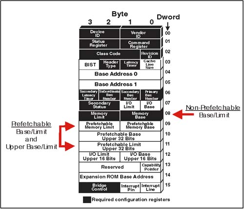 Table 16-4. Bridge Memory And Prefetchable Base And Limit Register Bit Fields | Register | Bits | Function | | Memory Base | 15:4 | Upper 12 bits of the 32 bit start address of non-prefetchable memory. Lower 20 bits are assumed to be 00000h. (Base address is always divisible by 1MB) | | | 3:0 | Bits 3:0 are reserved. | | Memory Limit | 15:4 | Upper 12 bits of the 32 bit ending address for non-prefetchable memory. Lower 20 bits are assumed to be FFFFFh. (Range is always in multiples of 1MB) | | | 3:0 | Bits 3:0 are reserved. | | Prefetchable Memory Base | 15:4 | Upper 12 bits of the 32 bit start address of prefetchable memory. Lower 20 bits are assumed to be 00000h. (Base address is always divisible by 1MB) | | | 3:1 | Bits 3:1 are reserved. | | | | Bit 0 = Size bit. If 1, Prefetchable Base Upper register provides an additional 32 bits of address (63:32). If Size = 0, Upper register not used. | | Prefetchable Memory Limit | 15:4 | Upper 12 bits of the 32 bit end address of prefetchable memory. Lower 20 bits are assumed to be FFFFFh. (Range is always divisible by 1MB) | | | 3:1 | Bits 3:1 are reserved. | | | | Bit 0 = Size bit. If 1, Prefetchable Limit Upper register provides an additional 32 bits of address (63:32). If Size = 0, Upper register not used. | | Prefetchable Base Upper | 31:0 | If Size bit in the Prefetchable Memory Base register is set = 1, this register provides the upper 32 bits of the 64 bit Prefetchable Base Address. If Size bit = 0, this register is not used. | | Prefetchable Limit Upper | 31:0 | If Size bit in the Prefetchable Memory Limit register is set = 1, this register provides the upper 32 bits of the 64 bit Prefetchable Limit Address. If Size bit = 0, this register is not used. | Memory And Prefetchable Memory Base/Limit Notes Bus-To-Bus Forwarding Rules The Memory and Prefetchable Base and Limit registers are used to decode memory transactions for the purposes of forwarding packets between the primary and secondary bus: -
Matching addresses on the primary bus in the HyperTransport memory mapped I/O range (Below FD_0000_0000h) are forwarded to the secondary bus. -
Non-matching addresses on the primary bus (including any above the memory mapped I/O range) are not forwarded downstream. -
Matching addresses on the secondary bus in the HyperTransport memory mapped I/O range (Below FD_0000_0000h) are not forwarded to the primary bus. If the bridge supports peer-to-peer transfers, it will reissue these requests onto the proper secondary bus in the event of an address match. -
Non-Matching addresses on the secondary bus (including any above the memory mapped I/O range) are forwarded to the primary bus. 64 Bit Addressing And The 40 Bit HyperTransport Space If memory addressing supports 64 bit addresses, then incoming HyperTransport requests must have the 40-bit address field 0-extended to 64 bits before comparison. To Disable Memory or Prefetchable Memory Decoding If either range is not required, software may program the appropriate base register with a value greater than its corresponding limit register. The Optional Address Remapping Registers In addition to the Memory and Prefetchable Memory Base and Limit registers just described, HyperTransport also supports an optional Address Remapping Capability Block which can be used to define additional downstream and upstream windows for positive address decoding. If implemented, these registers augment the memory Base/Limit registers in the bridge header. Refer to Chapter 21, entitled "Address Remapping," on page 477 for a discussion of address remapping. I/O Base And Limit Registers Dwords 07 and 12. HyperTransport memory maps I/O transactions into a special address range (FD_FC00_0000h to FD_FD_FFFFh). Once a device performs the 40-bit address decode and determines the request targets I/O, only the lowest 25 bits of the address field are considered valid. All bits above bit 24 are treated as "0", then a comparison is made using the I/O Base/Limit registers described here. Note that the I/O Base and Limit registers at Dword 7 only cover I/O requests in the lower 64KB range; an extra pair of registers (Upper I/O Base and Limit) allow extending the bridge I/O decode range to 32 bits for better PCI compatibility. The 25 bit valid I/O address limit still applies. Figure 16-6 on page 420 depicts the I/O Base/Limit and Upper Base/Limit registers; Table 16-5 on page 421 provides definitions for each of the register fields. Figure 16-6. HyperTransport Bridge I/O Base And Limit Register 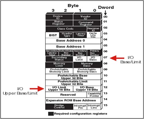 Table 16-5. Bridge I/O Base And Limit Register Bit Fields | Register | Bits | Function | | I/O Base | 7:4 | Upper 4 bits of the 16 bit start address of I/O. Lower 12 bits are assumed to be 000h. (Base address is always divisible by 4KB) | | | 3:1 | Bits 3:1 are reserved. | | | | Size bit. If set = 1, the I/O Base Upper Register will supply the upper 16 bits of I/O Base address (32 bits total= 4GB) | | I/O Limit | 7:4 | Upper 4 bits of the 16 bit ending address for I/O. Lower 12 bits are assumed to be FFFh. (Range is always in multiples of 4KB) | | | 3:1 | Bits 3:1 are reserved. | | | | Size bit. If set = 1, the I/O Limit Upper Register will supply the upper 16 bits of I/O Limit address (32 bits total= 4GB) | | I/O Base Upper | 15:0 | If Size bit in the I/O Base register is set = 1, this register provides the upper 16 bits of the 32 bit I/O Base Address. If Size bit = 0, this register is not used. | | I/O Limit Upper | 15:0 | If Size bit in the I/O Limit register is set = 1, this register provides the upper 16 bits of the 32 bit I/O Limit Address. If Size bit = 0, this register is not used. | Base/Limit Notes Bus-To-Bus Forwarding Rules -
Matching I/O addresses on the primary bus are forwarded to the secondary bus; they are ignored if generated on the secondary bus. -
Non-Matching I/O addresses on the primary bus are not forwarded to the secondary bus. -
Matching I/O addresses on the secondary bus are not forwarded to the primary bus. If the bridge supports peer-to-peer transactions, it will reissue these requests downstream on the proper chain. -
Non-Matching addresses on the secondary bus are forwarded to the primary bus. To Disable I/O Decoding Software may program the I/O Base Register with a value greater than the I/O Limit Register to disable I/O decoding. Bridge Control Register Dword 15. The Bridge Control register is used to manage the bridge secondary bus. If the secondary bus in the bridge is HyperTransport, many of the Bridge Control register bits used by PCI-PCI bridges are not used and tied to "0" as shown in Figure 16-7 on page 422; refer to Table 16-6 on page 423 for definitions of the active bits. Figure 16-7. HyperTransport Bridge Control Register 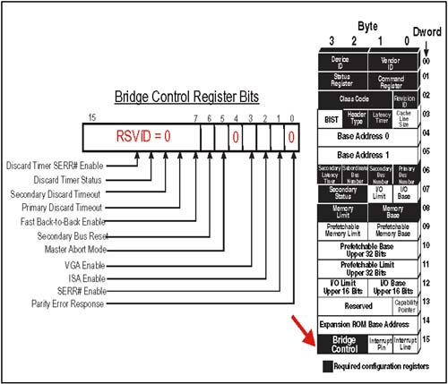 Table 16-6. HyperTransport Bridge Control Register Bit Fields | Bit | Function | | 1 | SERR# Enable. When set =1, a HyperTransport Sync flood event detected by the bridge on its secondary bus will be propagated onto the primary bus. If the secondary bus is PCI or PCI-X, an SERR# detected on the secondary bus will be propagated on the HyperTransport primary bus as a Sync flood. Warm Reset = 0. | | 2 | ISA Enable. (ISA alias control). When set = 1, this bit causes transactions targeting bytes 256d - 1023d of each 1KB range within the first 64KB of I/O space to be blocked from passing from primary to secondary bus (regardless of I/O Base/Limit register setting). Addresses in these ranges which originate on the secondary bus will be forwarded to the primary bus. This bit is required for PCI compatibility. Warm Reset = 0. Note: if address remapping is in use, the address decoding of the bridge may be undefined when this bit is set = 1. | | 3 | VGA Enable. When set = 1, RdSized and WrSized requests in the address range 0_000A0000h - 0_000BFFFFh (video buffer) will be forwarded from primary to secondary bus; they will be ignored by the bridge if generated on the secondary bus. I/O accesses in the first 64KB which alias to the ranges 3B0-3BBh or 3C0-3DFh (bits 9:0) will similarly be forwarded from primary to secondary buses. They, too, will be ignored by the bridge if generated on the secondary bus. Warm Reset = 0. Note: if address remapping is in use, the address decoding of the bridge may be undefined when this bit is set = 1. | | 5 | Master Abort Mode. This bit sets the policy to be used on the originating bus when a transaction forwarded to the destination bus ends in a master abort (error response with NXA set). When this bit set = 1, a master abort on the target bus will result in a target abort (error response with NXA set) on the originating bus. When this bit is = 0, a master abort error on the target bus will not be reported on the originating bus (normal response). If the request was a read, the bridge will drive all bytes in the data packet = FFh in either case. Warm Reset = 0. | | 6 | Secondary Bus Reset. This bit, required if the primary bus is HyperTransport, allows the generation of a secondary bus reset under software control. Writing the bit = 1 begins the reset sequence; clearing the bit removes the secondary bus reset. If the secondary bus is HyperTransport, this bit may be used in conjunction with the Warm Reset bit in the Host/Secondary Interface Command register to generate either a warm or cold reset event. Warm Reset = 0. | | Other Bits | All other Bridge Control Register bits are unused and should be tied to a low level. | Other Fields In The Header Primary Latency Timer Register This register is not implemented by HyperTransport devices. Should return 0's if read by software. If primary bus is PCI or PCI-X, use of this register follows that protocol. Base Address Registers The two Base Address Registers (BARs) are used by bridges in much the same way as for PCI bridge devices, with the following limits if the primary interface is HyperTransport: I/O BAR For an I/O request, a single BAR is implemented. Only the lower 25 bits of the value programmed into the BAR is used for address comparison by the target, and the upper bits of the BAR should be written to zeros by system software. Any I/O request packet sent out on a link should have the start address bits 39-25 programmed for the I/O range in the HyperTransport memory map. Memory BAR A request for memory using 32-bit addressing can be accomplished using a single BAR, just as in PCI. This would limit the assigned target start address for the device to the lower 4GB of the 1 TB (40 bit) HyperTransport address map. Optionally , a HyperTransport device may support 64 bit address decoding, and use a pair of BARs to support it. If this is done, only the lower 40 bits of the 64 bit BAR memory address will be valid, and the upper bits are assumed to be zeros. Memory windows for HyperTransport devices are always assigned in BARs on 64-byte boundaries; this assures that even the largest transfer (16 dwords/64 bytes) will never cross a device address boundary. This is important because HyperTransport does not support a disconnect mechanism (such as PCI uses) to force early transaction termination. Capabilities Pointer This field contains a pointer to the first advanced capability block. Because all HyperTransport bridge devices have at least one advanced capability, this register is always implemented. The pointer is an absolute byte offset from the beginning of configuration space to the first byte of the first advanced capability register block. Interrupt Line Register The HyperTransport specification indicates that this register should be read-writable and may be used as a software scratch pad. The information routing information programmed into this register in PCI devices isn't required in HyperTransport because interrupt messages are sent over the links and sideband interrupts are not defined. If the primary bridge interface is PCI or PCI-X, this register is used by software to program the system interrupt mapped to this device. Interrupt Pin Register This register is reserved in the HyperTransport Specification. It may optionally be implemented for compatibility with software which may expect to gather interrupt pin information from all PCI-compatible devices. If the primary bus interface is PCI or PCI-X, this register is hard-coded with the interrupt pin driven by this device (if any). Cache Line Size Register This register is not implemented by HyperTransport devices. If both interfaces are HyperTransport, bit should be tied low and read back as 0's if read by software. If either interface is PCI, this register is read-write. |