| In this activity, you will practice some simple exercises to get a feel for the LabVIEW environment. Try to do the following basic things on your own. If you have any trouble, glance back through the chapter for clues. | | 1. | Open a new VI and toggle between the front panel and block diagram.

Use the keyboard shortcuts listed in the pull-down menus! | 2. | Resize the windows so that both front panel and block diagram are visible simultaneously. You may need to move them around.
Do this using the standard resizing technique for your platform. Another hint: Try the Tile function! | | | 3. | Drop a numeric control, a string control, and a Boolean indicator on the front panel by selecting them from the Controls palette.
To get the numeric control, click on the Numeric button in the Modern category of the Controls palette and select Numeric Control from the subpalette that appears (see Figure 3.75).
Figure 3.75. The Modern>>Numeric palette showing the Numeric Control as well as other numeric controls and indicators 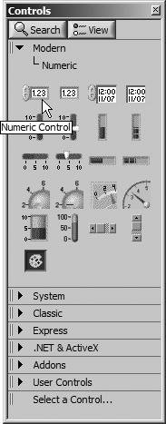
Now click your mouse on the front panel in the location where you want your digital control to appear. Voilàthere it is! Now create the string control and Boolean indicator in the same fashion (see Figure 3.76).
Figure 3.76. Your front panel after adding numeric, string, and Boolean controls 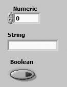
Notice how LabVIEW creates corresponding terminals on the block diagram when you create a front panel object. Also notice that floating-point numeric terminals are orange (integer numerics will be blue), strings are pink, and Booleans are green. This color-coding makes it easier for you to distinguish between data types.
| 4. | Now pop up on the digital numeric control (by right-mouse-clicking on Windows and Linux or <command>-clicking on Mac) and select Change to Indicator from the pop-up menu. Notice how the appearance of the numeric changes on the front panel (the little up and down arrows go away). Also notice how the terminal on the block diagram changes (the border is much thinner for indicators). Switch the object back and forth between control and indicator until you can easily recognize the differences on both front panel and block diagram. Note that for some objects (like a few Booleans), front panel indicators and controls can look the same, but their block diagram terminals will always be different.
| 5. | Choose the Positioning tool from the floating Tools palette, and then select an object on the front panel. Hit the <delete> key to remove it. Delete all front panel objects so you have an empty front panel and block diagram.

Positioning Tool
| | | 6. | Drop another digital control from the Numeric subpalette of the Controls palette onto the front panel. If you don't click on anything first, you should see a little box above the control. Type Number 1, and you will see this text appear in the box. Click the Enter button on the Toolbar to enter the text. You have just created a label. Copy the digital control, Number 1, to the clipboard by selecting it with the Positioning tool and then selecting Edit>>Copy from the menu. Then de-select Number 1 by clicking on an empty location of the front panel. Paste a copy of Number 1 onto the front panel by selecting Edit>>Paste from the menu. Note that LabVIEW has auto-incremented the name of the new control to Number 2. Create a digital indicator labeled N1+N2 and a digital indicator labeled N1-N2.

Enter Button

Operating Tool
Use the Operating tool to click on the increment arrow of Number 1 until it contains the value "4.00." Give Number 2 a value of "3.00" (see Figure 3.77).
Figure 3.77. Your front panel after adding the numeric controls and indicators and setting the control values 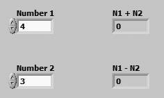
| 7. | Switch back to the diagram. Drop an Add function from the Numeric subpalette of the Functions palette in the block diagram (this works just like creating front panel objects). Now repeat the process and drop a Subtract function.
| | | 8. | Pop up on the Add function and select the Visible Items>>Terminals option (you'll notice that before you select it, the option is not checked, indicating that terminals are not currently shown). Once you show them, observe how the input and output terminals are arranged; then redisplay the standard icon by again selecting Visible Items>>Terminals (this time, the option appears with a checkmark next to it, indicating that terminals are currently shown).
| 9. | Bring up the Help window by using either the keyboard shortcut or the Show Context Help command from the Help menu. Position the cursor over the Add function. The Help window provides valuable information about the function's use and wiring pattern. Now move the cursor over the Subtract function and watch the Help window change.
| 10. | You may have to use the Positioning tool to reposition some of the terminals, as shown in Figure 3.78. Then use the Wiring tool to wire the terminals together. First select it from the Tools palette, and then click once on the numeric control's terminal and once on the appropriate terminal on the Add function to draw a wire. A solid orange line should appear. If you mess up and get a dashed black line instead of a solid orange one, select the wire fragment with the Positioning tool and hit the <delete> key; then try again. Click once and release to start the wire, click any time you want to tack a new segment (which turns a corner), and click on a destination to finish the wire.

Wiring Tool
Figure 3.78. Your block diagram after positioning the terminals and functions and wiring everything up 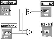
Notice that when you pass the Wiring tool over the Add and Subtract functions, little wire stubs appear, showing where the terminals are located. In addition, as you pass the cursor over a terminal, its name appears in a tip strip. Like learning to type, wiring can be kind of tricky until you get the hang of it, so don't worry if it feels a little awkward right now!
| | | 11. | Switch back to the front panel and pop up on the icon pane (the little window in the upper-right corner). Select Show Connector from the menu (see Figure 3.79). Observe the connector that appears. If you can't get the pop-up menu to appear, you are probably trying to pop up in the icon pane of the block diagram.
Figure 3.79. The Show Connector option, accessible from the pop-up menu of the VI's icon pane 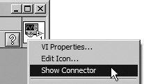
Now pop up again on the connector and look at its menu to see the configuration options you have. The connector defines the input and output parameters of a VI so that you can use it as a subVI and pass data to it. You can choose different patterns for your connectors depending on how many parameters you need to pass.
As you learned in the earlier section, "SubVIs, the Icon, and the Connector," it is usually best to use the default connector (having 12 terminals) so that you have extra terminals, should you add controls or indicators to your subVI at a later time. Show the icon again by selecting Show Icon. Remember, the icon is just the pictorial representation of a VI; when you use a VI as a subVI, you will wire to this icon in the block diagram of the top-level VI just like you wired to the Add function.
| 12. | Run the VI by clicking on the Run button. The N1+N2 indicator should display a value of "7.00" and N1-N2 should be "1.00." Feel free to change the input values and run it over and over.

Run Button (Active)
| 13. | Save the VI by selecting Save from the File menu. Call it Add.vi and place it in your MYWORK directory.
|
Congratulations! You have now mastered several important basic LabVIEW skills! |