Selecting and Configuring DAQ Measurement Hardware
Choosing Your HardwareOnce you know what kind of signals you want to measure and/or generate, it's time to choose a plug-in DAQ device (assuming a DAQ device will meet your requirements), such as those shown in Figure 10.25. Generally speaking, we recommend always using a National Instruments device if you're going to use LabVIEW. National Instruments offers a huge selection of all types of DAQ devices with a good selection of buses, platforms, performance, functionality, and price range. You can browse their catalog online (http://ni.com), where you will find a "DAQ Designer" utility that will help you determine what hardware suits your needs. If you do find a DAQ device from a company other than National Instruments, make sure they provide a LabVIEW driver with it. Figure 10.25. DAQ devices in a variety of form factors and bus types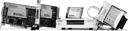 To pick the best hardware for your system, you need to understand well what your system requirements are, most noticeably the "I/O count" (how many inputs and how many outputs). The following checklist should be useful in determining if you have all the information you need to select a DAQ device:
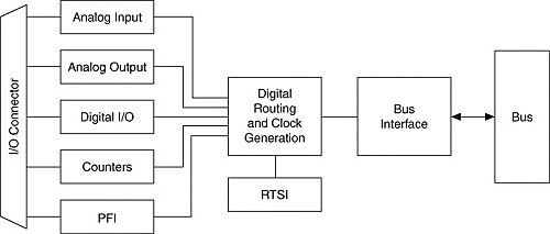
By answering these questions, you'll be in a better position to choose a suitable DAQ device. At the time of this writing, a popular type of National Instruments device is the so-called M Series device, which is a "multi-function" device. A multifunction DAQ device like an M Series device will provide you with analog inputs, analog outputs, digital I/O, and often at least one counter/timer, making it useful for a wide range of applications (see Figure 10.26). Figure 10.26. Multi-function M Series DAQ device from National Instruments The analog input section of a multifunction device consists of the ADC and the analog input circuitry. The analog input circuitry contains the analog multiplexer, the instrumentation amplifier, and the sample-and-hold circuitry. For more detailed information on the ADC, refer to the manual that accompanies your DAQ device. What about cost? Plug-in DAQ devices range in price from about $100 (U.S.) for low-cost USB devices to $5000 (U.S.) (or more) for extremely high-end devices. In general, three factors are directly proportional to and most influential on the price: the communication bus, the sampling rate, and the number of analog I/O channels. So if you are making DC measurements, there's no need to shell out extra dough for a device with a 10-MHz sampling rate. Also, digital I/O is usually cheap. The device prices shouldn't really seem expensive once you pause to consider what you're getting, however. How much would an oscilloscope, spectrum analyzer, strain gauge meter, and hundreds of other instruments all together cost you if you had to buy them as "non-virtual" instruments? Don't forget: One of the best resources to help you figure out what hardware you need is the online utility from National Instruments called DAQ Designer. Look for it on http://ni.com. If you want to look at a broader range of options, you should consult with an experienced system integration company who can advise you on what works best for you. Activity 10-2: Measurement System AnalysisFollowing are a couple of more challenging signal measurement problems. Your objective is to specify the needed information. Answer the following for each scenario:
The answers are at the end of the chapter. Installing DAQ Device Driver SoftwareAll devices that your computer communicates with use drivers, nasty and painful pieces of low-level code that convince your computer that the devices are connected and can be used. The good news is that, assuming your drivers are installed properly, you should not have to really mess with them to use your DAQ device. All National Instruments DAQ devices come with driver software, collectively referred to as NI-DAQmx. In fact, NI-DAQmx is installed by default when you install LabVIEW, so if you have the full version of LabVIEW, chances are it's already on your machine. Between NI-DAQmx and LabVIEW, there is a utility called MAX (Measurement & Automation Explorer). MAX is a Windows software interface that gives you access to all your National Instruments devices (whether they are DAQ, GPIB, VXI, and so on). MAX is mainly useful for configuring and testing your hardware. This is very useful to do before you try to access the hardware in LabVIEW. Again, MAX is installed by default when you installed LabVIEW; you should see the shortcut icon on your Windows desktop (see Figure 10.27). Figure 10.27. Measurement & Automation shortcut that launches MAX (on Windows) We'll talk more about MAX briefly.
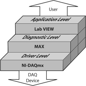
MAX is a utility available on Windows only. For configuring DAQ devices on other operating systems, such as the Mac OS X or Linux, use the NI-DAQmx or NI-DAQmx Base configuration utility provided for that OS. Figure 10.28 shows the conceptual relationship between an NI-DAQmx Device, NI-DAQmx, MAX, LabVIEW, and the user. Figure 10.28. The conceptual relationships connecting the user to the DAQ Device Measurement & Automation Explorer (MAX)MAX, shown in Figure 10.29, is mainly used to configure and test your National Instruments hardware, but it does offer other functionality such as checking to see if you have the latest version of NI-DAQmx installed. Figure 10.29. The MAX configuration utility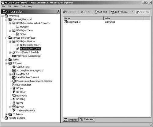
If you are using Mac OS X or Linux, the previous section on MAX doesn't apply, because, at least at press time, MAX was a Windows-only utility. However, NI-DAQmx and NI-DAQmx Base have driver configuration utilities for the supported platformsoften these are command-line tools. You should check the documentation for information on installing and configuring your hardware. Next, we will show you how to configure your DAQ devices to quickly take useful measurementswe will do all of this from within MAX. NI-DAQmxNI-DAQmx is a cross-platform driver for National Instruments DAQ devices. NI-DAQmx supersedes the older Traditional NI-DAQ (previously referred to as "NI-DAQ") and provides the following improvements over Traditional NI-DAQ:
Bottom-line: It makes your life easier by helping you achieve your DAQ objectives with less work and better results! At the time of this book's writing, NI-DAQmx is supported on Windows and Linux. It seems likely that Mac OS X will also be supported some time in the future. If you would like to use National Instruments DAQ devices on platforms that are not currently supported by NI-DAQmx, consider using NI-DAQmx Base, which is supported on Windows, Linux, Mac OS X, and Pocket PC.
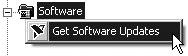
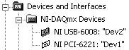
NI-DAQmx Base offers only a subset of NI-DAQmx functionality on Windows, Linux, Mac OS X, and Pocket PC OSs. The LabVIEW VIs provided with NI-DAQmx Base are similar to the NI-DAQmx VIs, but they are not interchangeable. Interestingly, the NI-DAQmx Base driver software was built almost entirely in LabVIEW, using register-level programming via the NI Measurement Hardware DDK (MHDDK). This architecture makes it easy to port to new platforms in the future. It will be a long time, if it ever happens, before NI-DAQmx Base provides all of the functionality of NI-DAQmx. But, as LabVIEW continues to evolve as a full-featured software development environment, this possibility is not out of the question. Before we move to the next sections, make sure that DAQmx is installed on your system. Do this by browsing to My System>>Software in the MAX Configuration panel. Find NI-DAQmx and mouse-click on it to select it. This will display the NI-DAQmx software version information in the Attributes pane, as shown in Figure 10.30. Figure 10.30. Verifying that NI-DAQmx is installed from within MAX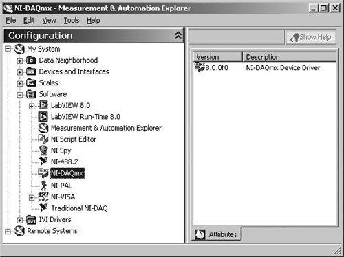 The MAX Software category shows all of your currently installed versions of National Instruments software. The icon for each software package is also a shortcut that you can use to launch the software. For example, you can right-click on the LabVIEW 8.0 icon and choose Launch LabVIEW 8.0 to launch LabVIEW. The Software category also includes a Software Update Wizard to check if your National Instruments software is the latest version. Right-click on the Software category icon and select Get Software Updates to run the Software Update Wizard (see Figure 10.31). If your software isn't the latest version, the Software Update Wizard will link you to a page on ni.com to download the latest version of your software. Figure 10.31. Checking for software updates in MAX Configuring NI-DAQmx Devices in MAXNow we are now going to show you how to configure your NI-DAQmx devices. If you don't have an NI-DAQmx device connected to your computer, you should know that NI-DAQmx supports simulated devices. So, if you don't have an NI-DAQmx device, jump ahead to the next section and add a simulated device. Then, come back here and we'll show you how to configure it just like you would a real device! Browse to the My System>>Devices and Interfaces>>NI-DAQmx Devices category in MAX. Beneath it you should see a list of all the physical and simulated NI-DAQmx devices connected to your system (as shown in Figure 10.32). Figure 10.32. NI-DAQmx devices in MAX, showing the physical and simulated devices connected to your system
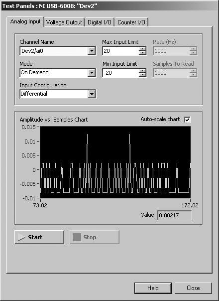
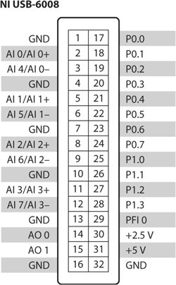
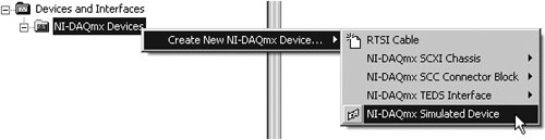
In addition to NI-DAQmx devices, the Devices and Interfaces category shows you any currently installed and detected National Instruments hardware, such as plug-in DAQ devices, SCXI and PXI chasses, GPIB controllers, and so on. Devices and Interfaces also includes utilities for configuring and testing your devices. We aren't going to show you how to configure every type of device. But hopefully, this section will give you enough experience to explore the rest of MAX comfortably. When you right-click on an installed NI-DAQmx device, the pop-up menu gives you the options: Self-Test, Test Panels, Reset Device, Create Task, Configure TEDS, Rename, Delete, Device Pinouts, Properties, and Self-Calibrate. The Self-Test option runs a brief test of device resources, and then presents a message window with the results of the test. The Test Panels window (shown in Figure 10.33) is used for testing the analog input, analog output, digital I/O, and counter functionality of your DAQ device. This is a great utility for troubleshooting because it allows you to test the functionality of your device directly from NI-DAQmx. If your device doesn't work in the Test Panel, it isn't going to work in LabVIEW. If you are ever having unexplainable trouble with data acquisition in a LabVIEW program, you can use the Self-Test and the Test Panels to make sure the device is working properly. Figure 10.33. Test Panels window The Reset Device option performs a hardware reboot of the device. A reset aborts any running tasks and restores the device to its default settings. The Create Task option creates an NI-DAQmx task, which you will learn about later in this section. The Configure TEDS option allows you to configure TEDS sensors connected to your DAQ device. TEDS stands for Transducer Electronic Data Sheets, and is an IEEE standard (IEEE 1451.4) for smart sensors that store their own calibration data and can communicate that information to the computer that is acquiring the electrical signal from the sensor. For more information on TEDS, visit http://www.ni.com/teds/. The Rename option allows you to change the name that you will use to address the device in LabVIEW. The names default to "Dev1," "Dev2," and so on. The Delete option will be disabled for plug & play physical devices, but will be enabled for simulated devices and accessories. The Device Pinouts option will open the NI-DAQmx Device Terminal help documentation, showing you the pin numbers for connecting physical signals to and from your DAQ device (see Figure 10.34). Figure 10.34. Device pinouts, as shown by the NI-DAQmx Device Terminal help documentation The Properties panel allows you to configure additional device-specific options such as power-up states, accessory, RTSI configuration, and so on. The Self-Calibrate option runs a self-calibration on devices that support calibration. NI-DAQmx Simulated DevicesEven if you do not have a DAQ device present on your system, don't let that stop you from learning how to configure and use DAQ devices in MAX, or how to program your DAQ application. NI-DAQmx allows you to add simulated devices to your system, configure and test them in MAX, and acquire data from them in LabVIEWit works just as if you had real hardware present! And, when you are ready to put the real hardware into your system, you can easily import the NI-DAQmx simulated device configuration to the physical device. To create an NI-DAQmx simulated device, complete the following steps within MAX:
If you are not sure which type of simulated device to create, choose a general purpose device with lots of different I/O. For example, the M Series 6221DAQ device has 16 analog inputs, two analog outputs, 24 digital I/O lines, and two counter/timersthis will allow you to test just about any type of data acquisition task.
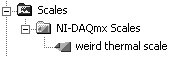
In MAX, the icons for NI-DAQmx simulated devices are yellow. The icons for physical (real) devices are green. To remove an NI-DAQmx simulated device, right-click the device and click Delete from the pop-up menu. Configuring Data AcquisitionWe will now discuss how to configure NI-DAQmx Scales, NI-DAQmx Virtual Channels, and NI-DAQmx Tasks in MAXthese are the key components to getting useful measurements into LabVIEW. A scale defines scaling information that can be used by virtual channels, virtual channels define real-world measurements consisting of one or more DAQ channels, and tasks define timing, triggering, and sample size information for acquiring data from virtual channels. NI-DAQmx ScalesA scale defines scaling information that can be used by virtual channels (see the Custom Scaling setting in the virtual channel's configuration panel). This is sometimes necessary or useful particularly for sensors that are not linear or where you want to read the actual units directly instead of having to convert voltage or current to the desired unit, such as temperature. Each custom scale can have its own name and description to help you identify it (see Figure 10.37). A custom scale can be one of four types: linear, map ranges, polynomial, or table, described as follows:
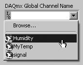
Figure 10.37. NI-DAQmx Scales in MAX NI-DAQmx Virtual ChannelsSo what is a virtual channel? Virtual channels define real-world measurements consisting of one or more DAQ channels (terminals on your DAQ device) along with other channel-specific informationrange, terminal configuration, and custom scalingthat is used to format the data. Most DAQ devices simply measure or generate electrical voltages or currents (analog voltages between -10V and +10V, analog currents between 20mA and 40 mA, digital voltages that are either 0V or +5V, and so on). However, when we want to measure physical phenomena like temperature, humidity, and wind-speed, we have to convert one or more electrical signals, as measured by our DAQ devices, into real-world measurements. This is what virtual channels do and why they are so powerful. You don't have to use virtual channels, of course. In your LabVIEW application, you can refer to device channels by their number (0, 1, 2, ...). But configuring them first as a virtual channel in MAX is handy because, as we'll see in the next chapter, you can use a LabVIEW front panel or block diagram DAQmx Global Channel ring that gives you the names of all your virtual channels, and you can even automatically generate LabVIEW VIs from your DAQmx Global Channel (see Figure 10.38)! Figure 10.38. Assigning a DAQmx Global Channel to a DAQmx Global Channel ring on the front panel of your VI To create a virtual channel, you right-click on the Data Neighborhood icon in MAX and choose Create New . . . . Select NI-DAQmx Global Virtual Channel and click Next. This will guide you through the steps to set up your virtual channel (see Figure 10.39). Figure 10.39. Create New . . . dialog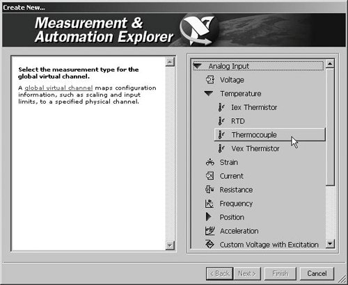 Voltage Input and Output SettingsWhen configuring virtual channels that use analog I/O, it is important to understand some of the parameters that control the operation of the ADC (analog-to-digital converter) and DAC (digital-to-analog converter). On almost all devices, you will configure these settings in the virtual channel or task settings panel (some very old boards require you to set jumpers on the board). The types of settings you can configure include parameters like range, input mode, reference, and polarity; for example, on most M Series devices, you can set the following:
NI-DAQmx TasksSometimes when you perform a measurement, you will need to coordinate the reading of data from one or more channels with timing and triggering events. An NI-DAQmx Task is a collection of one or more virtual channels along with timing, triggering, and other properties. Conceptually, a task represents a measurement or generation you want to perform. For example, a task allows you to specify whether you want to measure 1 sample, measure N samples, or measure continuously (using a buffer to store data). A task also allows you to specify the sample rate, the timing clock source, and the task triggers. Once you have defined a task, you can simply start the task, read the task data, and stop the task from within LabVIEW. We'll talk about NI-DAQmx Tasks in further detail in Chapter 11. |


EAN: 2147483647
Pages: 294
- Chapter VII Objective and Perceived Complexity and Their Impacts on Internet Communication
- Chapter X Converting Browsers to Buyers: Key Considerations in Designing Business-to-Consumer Web Sites
- Chapter XI User Satisfaction with Web Portals: An Empirical Study
- Chapter XII Web Design and E-Commerce
- Chapter XIII Shopping Agent Web Sites: A Comparative Shopping Environment