6.6 SAN Backup Topologies
| only for RuBoard - do not distribute or recompile |
6.6 SAN Backup Topologies
It is fairly simple to integrate tape libraries into the SAN, although there are certain connectivity limitations. However, tape library technology is changing every day, so these limitations may soon disappear.
6.6.1 Connectivity Limitations
Almost all tape libraries are SCSI devices. Integrating them into a SAN requires FC/SCSI bridges. The topology examples in this section show bridges in use.
HP s largest tape library is no exception. The descriptive material for the SureStore E Tape Library 20/700 says the device is part of the HP Equation architecture, integrating with SureSpan Fibre Channel bridges [italics added] and hubs for flexible configurations, speed, and distance, with SureDesign Storage Node Manager for proactive diagnostics and centralized management.
However, things are changing. As this book goes to press, manufacturers are starting to announce native Fibre Channel tape libraries for SANs.
6.6.2 Hub Limitations
Tape libraries do not do well on a Fibre Channel Arbitrated Loop (FC-AL). Connecting the tape library to a switch is a far better choice.
Why? The first concern is bandwidth. Fibre Channel Arbitrated Loop allows up to 126 node ports to be connected to the loop. There is a single connection between a pair of ports at any point in time. Since the loop s bandwidth is shared by all participating ports on the loop, any individual port will be able to realize only a portion of the rated bandwidth. For the time the two ports own the loop, they get all the bandwidth, but they don t own the loop all the time.
This differs from a Fibre Channel switched-fabric topology, in that ports on the fabric take full bandwidth without sharing. A fabric switch currently costs about four times as much as a hub (about 2.5 to 3 times as much per port).
The second concern is the potential for interrupting the backup operation. In a Fibre Channel Arbitrated Loop, a tape backup in progress can be interrupted by the dynamics of the FC-AL (for example, a LIP occurs when a server is power cycled).
Error handling in the backup application needs close attention to ensure that data loss doesn t occur and that a failed command is recoverable. To prevent a backup or restore operation failure, the backup application software must be able to recover from such a change on the loop.
FC-AL activities, such as power-cycling servers, hot-plugging devices, error states, and other changes can be factors that can cause the system to rearbitrate or cause a LIP to occur. This might interfere with the data transfer to a tape.
A LIP can cause a SCSI command to fail, thereby causing a backup failure. The application informs the operator that the tape operation has failed. To avoid the chance of a tape backup failure, the system administrator must select applications that can handle error recovery and a system environment with stable conditions.
To avoid all this, try one of the following:
-
Connect the tape library directly to a server
-
Connect the tape library directly to a server using a bridge
-
Connect the tape library to a hub of its own
-
Connect the tape library to a fabric switch
6.6.3 Straightforward Backups
Let s begin with a Fibre Channel version of a traditional attached-device SCSI configuration (Figure 6-7).
Figure 6-7. Fibre Channel Server Backup
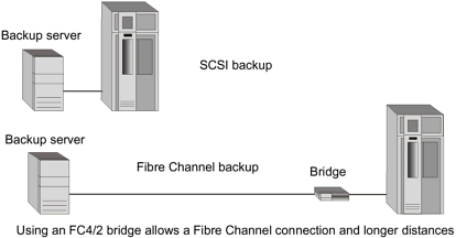
There is an advantage in distance between devices, providing a distance of up to 500 meters between the server and the bridge, plus another 25 meters of SCSI cable at the tape library end. This permits you to locate the tape library in a separate room or on a separate floor.
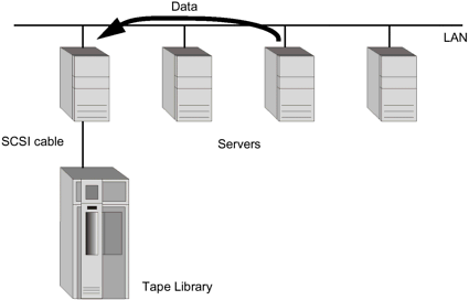
Backup of other servers takes place by passing data through the backup server over the LAN.
What do we mean by over the LAN?
When traditional backup is done over the LAN (Figure 6-8), data on embedded disks and directly-attached storage makes its way to the tape library over the LAN connection. Throughput is slower for the backup, and network bandwidth is consumed. Clients who were already feeling performance bottlenecks will feel them more intensely.
Figure 6-8. Backup Over the LAN
6.6.4 Device Sharing
The backup possibilities are more flexible with Fibre Channel and a bridge (Figure 6-9). The FC4/2 bridge makes it easy for two servers to share a tape library.
Figure 6-9. Two Servers Share One Tape Library
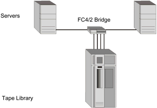
Both servers can be backed up without requiring data to move across the LAN. Other servers in the configuration would still be backed up over the LAN.
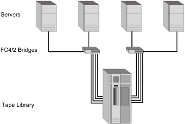
However, if we use two FC 4/2 bridges, we can allow four servers to share a tape library (Figure 6-10).
Figure 6-10. Four Servers Share a Tape Library
6.6.5 Backing Up the SAN
But where, you might ask, has the SAN gone? It s still there, as the following illustration shows.
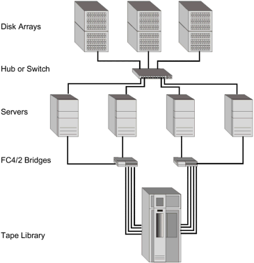
In this configuration (Figure 6-11) all servers share all disk devices. They also all access a tape library. It s a high performance backup solution, and backup traffic is eliminated from the LAN.
Figure 6-11. Backup Topology with a SAN
6.6.6 Vaulting
Your site may require vaulting of secondary storage devices and media in a different room or building than the servers. Here is a distance solution that requires only switches and bridges.
(The SAN storage devices are not illustrated .)
In Figure 6-12, the distance attainable is 10 km over a Fibre Channel connection, using switches. It s a switched, full-bandwidth solution. It provides for double pathing and two libraries in the vault.
Figure 6-12. Two Servers and Two Tape Libraries
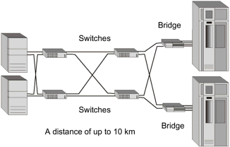
Backup of the two servers shown and SAN storage takes places directly. Backup of embedded storage in other servers still takes place over the LAN.
6.6.7 Zero Downtime Backup
A high-end disk array, such as the XP256, has capabilities that can improve the backup process by shortening backup time and making it possible for more frequent snapshots of the data to be taken.
Zero Downtime Backup (sometimes called Zero Impact Backup) requires installation of the HP Business Copy XP software on the system and HP s OmniBack II software.
Zero Downtime Backup would be an ideal scenario for SAP R/3 and Oracle databases. The users can continue to access their data during backup. In addition, we would hope for minimum performance degradation for the Oracle and SAP R/3 databases.
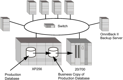
The solution shown in Figure 6-13 provides a comprehensive split-mirror backup to separate the production environment from the backup and recovery environment. Business Copy XP creates mirror images of active production volumes . Then OmniBack II performs a backup on the business copy, while the database applications continue to run with no performance degradation.
Figure 6-13. Zero Downtime Backup
A zero impact backup includes the following five steps:
-
The database is put into backup mode. This guarantees a consistent version of the data on the business copy.
-
OmniBack II initiates a split of the ongoing mirroring of data between the source and the target volumes.
-
After a successful split, the database can be taken out of backup mode.
While the database is in backup mode, the application can still access the data, but performance is slightly decreased during this process. Usually, the database is in backup mode for about five to ten minutes.
-
Now the OmniBack II backup server can perform the backup from the business copy. This process is totally independent from the application host.
-
When the backup is finished the mirror can be resumed and the business copy of the data is resynchronized with the database.
6.6.8 Disaster Recovery
For full disaster recovery, HP SureStore E Continuous Access XP software mirrors data transactions from a primary XP256 to a target XP256, typically in a separate location (Figure 6-14).
Figure 6-14. Disaster Recovery with Continuous Access XP
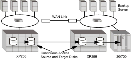
The target XP256 may also run SureStore E Business Copy XP software, so the remote site will perform the backup from the business copy.
The OmniBack II backup software allows the backup to be conducted on the remote XP256 disk array at the disaster recovery site. Both the active business application at the local site and the backup process at the remote site retain maximum throughput and full performance. The backup server is attached to the target XP256.
| only for RuBoard - do not distribute or recompile |
EAN: 2147483647
Pages: 88