Section 5.4. Building the Gaming PC
5.4. Building the Gaming PCFigure 5-1 shows the major components of the gaming PC. The Antec P150 case is flanked on the left by the nVIDIA video adapter, and on the right by the ASUS motherboard. In front, left to right, are the two 500 GB Seagate hard drives, the BenQ optical drive, the AMD CPU cooler, and the Kingston DDR2 memory modules. The Samsung display, Logitech speakers, and the other external peripherals are not shown. Figure 5-1. Gaming PC components, awaiting construction Before you start building the system, verify that all components are present and accounted for. We always remind readers to do that, but for some reason we often forget to do it ourselves. 5.4.1. Preparing the CaseTo begin preparing the case, place the Antec P150 upright on the work surface and loosen the captive thumbscrews that secure the left side panel, as shown in Figure 5-2. Figure 5-2. Loosen the thumbscrews that secure the left side panel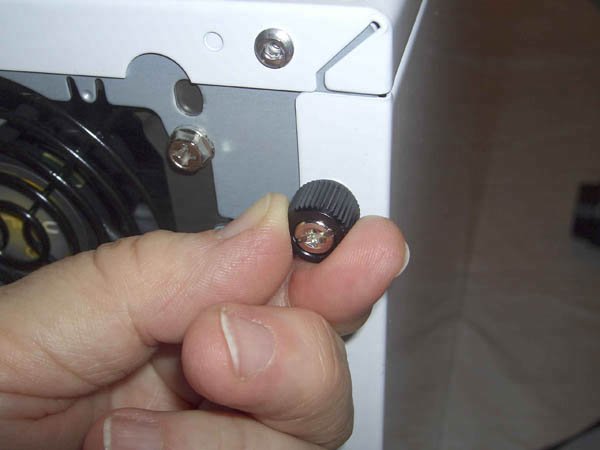 Warning: Before you do anything else, check the back of the power supply to see if it has an input voltage switch. Auto-sensing power supplies (like the Antec NeoHE 430 we used) automatically detect the input voltage and set themselves for 120V or 240V operation. Other power supplies must be set manually for the correct input voltage. If you see a voltage switch, make sure it's set for the correct voltage.If you connect a power supply set for 240V to a 120V receptacle, no harm is done. The PC components receive half the voltage they require, and the system won't boot. But if you connect a power supply set for 120V to a 240V receptacle, the PC components receive twice the voltage they're designed to use. If you power up the system, that overvoltage destroys the system instantly in clouds of smoke and showers of sparks.
Swing the rear of the panel away from the case, as shown in Figure 5-3, and lift it free. Place the side panel aside, where it won't be scratched. Figure 5-3. Remove the left side panel and set it aside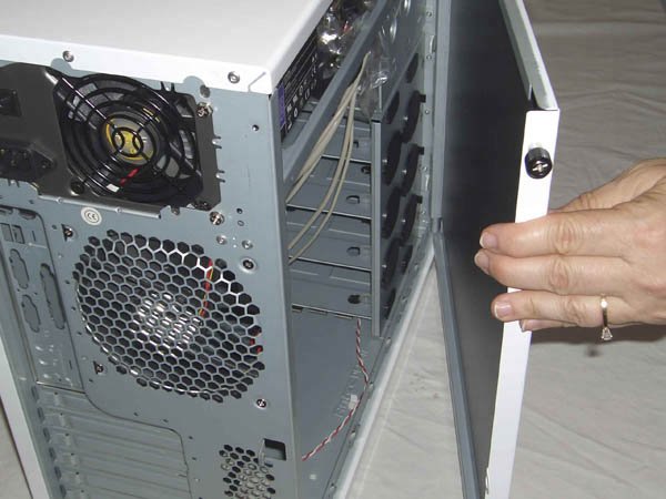 You'll see a large plastic bag in the drive bay. This bag contains various cables and small parts. Antec apparently wants to make very sure that bag stays in place during shipping, because they secure it with a plastic cable tie. Use your diagonal cutters or a sharp knife to sever the cable tie, as shown in Figure 5-4. Remove the plastic bag from the drive bay and unseal it. Some of the parts you'll need right away. Others you'll need later, or not at all. Figure 5-4. Snip the cable tie that secures the plastic parts bag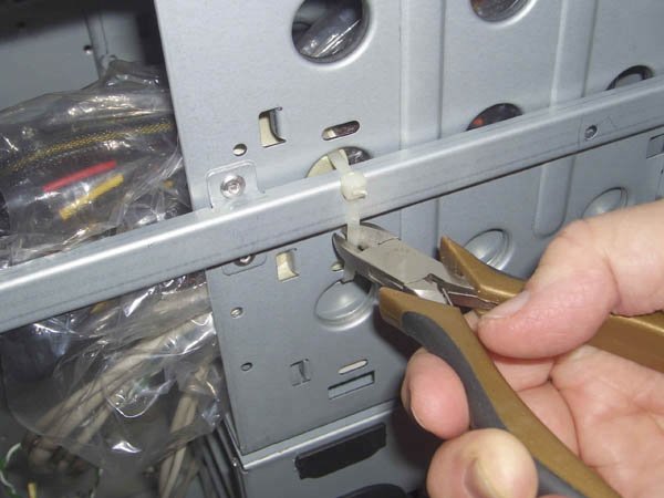 The front bezel of the case is held in place by three plastic tabs along the inside left-front edge of the chassis. Press each one of these tabs toward the outside of the case to unlatch the bezel, as shown in Figure 5-5. Figure 5-5. Press the three locking tabs to unlatch the front bezel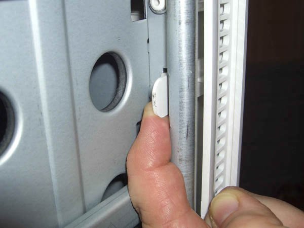 With all three plastic tabs unlatched, the bezel is free to rotate. Swing the left side of the bezel away from the case until it is at about a 45° angle, as shown in Figure 5-6. Then lift the right side of the bezel straight up about an inch, as shown in Figure 5-7, and pull the bezel free from the case. Figure 5-6. Swing the left side of the front bezel away from the chassis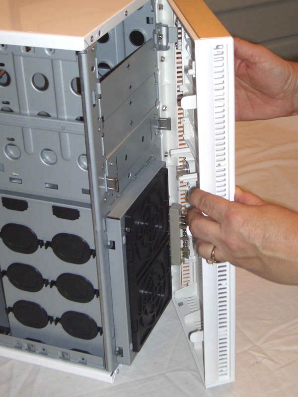 Figure 5-7. Lift the right side of the bezel up about an inch and then remove it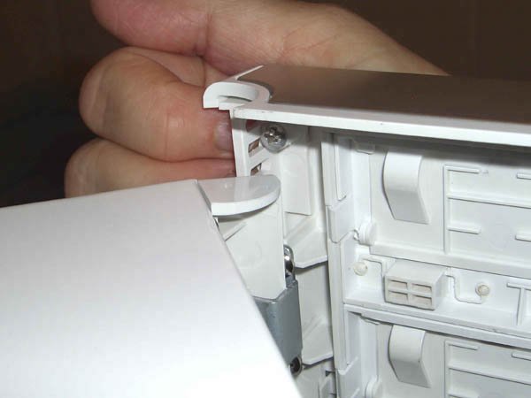
The NeoHE 430 power supply arrives installed in the P150 case. The NeoHE 430 uses Antec's patented cable management system. Only the main ATX power cable and the ATX12V power cable are permanently attached to the power supply. All other cables are optional, so you can install only the cables you need. The optional power cables plug into one of the five proprietary 6-pin sockets on the power supply, as shown in Figure 5-8. Any of the optional cables can be connected to any of the sockets. Antec supplies three types of optional cables, which are stored in the large plastic bag you removed earlier:
Figure 5-8. Connect the optional cables to the power supply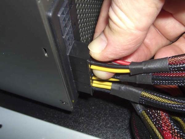 Antec also provides a short Y-adapter cable that connects to a Molex (hard drive) power connector on one end and provides two Berg (floppy drive) power connectors on the other. We had no need of that adapter, because we didn't install a floppy drive or any other component that uses the Berg connector in our gaming PC. Our system requires one of each type of cable. The two S-ATA Seagate hard drives will receive power from one of the optional S-ATA power cables. The optical drive and rear case fan will receive power from one of the optional Molex power cables. The video adapter requires supplemental power, which it receives from the optional PCI Express power cable. We connected those three cables, as shown in Figure 5-8, leaving two of the proprietary 6-pin power supply connectors unused.
Like nearly all cases, the Antec P150 comes with a generic back-panel I/O template installed. As usual, this generic template doesn't match the back-panel I/O ports on the motherboard, so the next step is to remove that template. The template installed in our case was wedged in very tightly. We eventually were able to pop it out using a screwdriver handle. Start in one corner, and be careful not to hurt yourself if the template suddenly pops free. The template is thin metal and has sharp edges. We didn't bend the template, but it was a near thing. Of course, it's not really the generic template we're concerned about. We have stacks of generic templates in a box in our workroom. (Robert never throws anything out.) But that template was well and truly stuck, and we were worried that we might bend the edge of the template cutout in the case. Fortunately, with a bit of patience we were able to remove the generic template without damaging the case. With the original template removed, the next step is to install the custom back-panel I/O template that's supplied with the motherboard. Before you do that, verify that the holes in the custom template match the ports on the motherboard I/O panel. Although it's rare, we have seen custom templates that don't match the motherboard they were supplied with. Once you've verified that you have the correct I/O template, install it in the template cutout in the case, working from inside the case. Align the template with the cutout and use a screwdriver handle to press gently along the edges and corners until it snaps into place, as shown in Figure 5-9. Figure 5-9. Align the back-panel I/O template and press gently until it snaps into place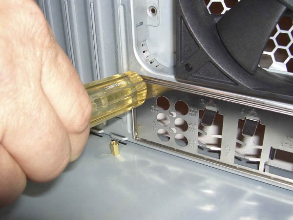
The next step is to install brass standoffs in the case to support the motherboard once it is installed. Examine the motherboard to locate all of the mounting holes. It's easy to miss a mounting hole or two in all the clutter on a typical motherboard, so we generally hold the motherboard up to a bright light, which makes the mounting holes stand out. Once you've located all the mounting holes (the ASUS M2N32-SLI Deluxe motherboard has nine), you need to make sure that standoffs are installed in each corresponding position on the motherboard tray. The easiest way to check this is to hold the motherboard in position above the case, as shown in Figure 5-10, and look straight down through each mounting hole to determine which motherboard screw holes should receive standoffs. Figure 5-10. Hold the motherboard above the case to determine where standoffs should be installed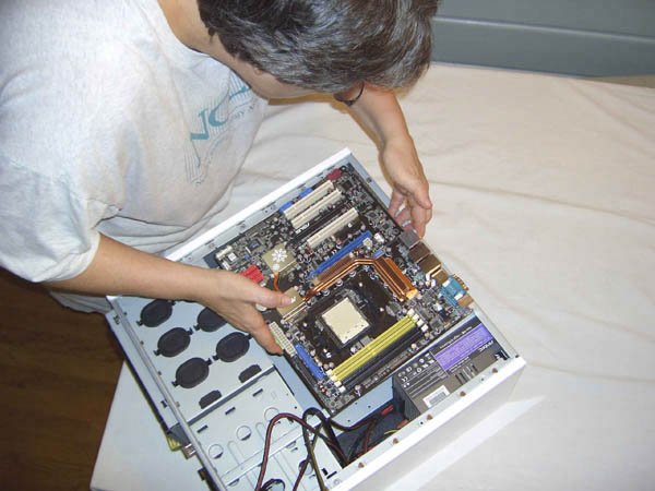
The Antec P150 case comes with four standoffs installed, all of which correspond to mounting holes in the ASUS M2N32-SLI Deluxe motherboard. That means we need to install five more standoffs in the vacant positions that match the mounting holes in the motherboard. Locate the plastic parts bag that contained the power supply cables you installed earlier. You'll find a small plastic bag with screws, standoffs, and other small parts. Set aside the five standoffs you'll need to install. While you're at it, locate nine motherboard mounting screws and set them aside as well. (You can verify you have the right screws by temporarily inserting one into a standoff.) Install the five additional standoffs into the positions you determined earlier. You can use your fingers to install the standoffs, but using a 5mm nutdriver as shown in Figure 5-11 makes the job much easier. If you do use a nutdriver, be careful not to apply too much torque. The standoffs are made of soft brass that is easily stripped. Tighten the standoffs only finger-tight. Figure 5-11. Install standoffs in each mounting position required by the motherboard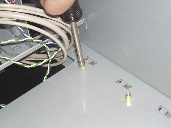 After you've installed the standoffs, temporarily slide the motherboard into position, as shown in Figure 5-12. Make sure that there's a standoff visible under each mounting hole, and that no extra standoffs are installed. After you've done that, remove the motherboard and set it on your work surface. Figure 5-12. Verify that every mounting hole has a standoff and that no extra standoffs are installed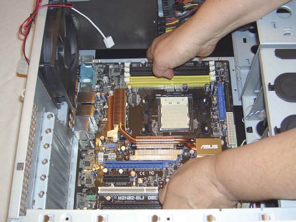
5.4.2. Populating the MotherboardIt is always easier to populate the motherboardinstall the processor and memorywhile the motherboard is outside the case. In fact, you must do so with some systems, because installing the heatsink/fan unit requires access to both sides of the motherboard. Even if it is possible to populate the motherboard while it is installed in the case, we always recommend doing so with the motherboard outside the case and lying flat on the work surface. More than once, we've tried to save a few minutes by replacing the processor without removing the motherboard. Too often, the result has been bent pins and a destroyed processor. 5.4.2.1. Installing the processorTo install the Athlon 64 X2 processor, lift the ZIF (zero insertion force) lever until it reaches vertical. With the arm vertical, there is no clamping force on the socket holes, which allows the processor to drop into place without requiring any pressure. Pin 1 is indicated on the processor and socket by small triangles. With the socket lever vertical, align pin 1 of the processor with pin 1 of the socket and drop the processor into place, as shown in Figure 5-13. The processor should seat flush with the socket just from the force of gravity, or perhaps with very gentle pressure. If the processor resists being seated, something is misaligned. Remove the processor and verify that it is aligned properly and that the pattern of pins on the processor corresponds to the pattern of holes on the socket. Never force the processor to seat. You'll bend one or more pins, destroying the processor. Figure 5-13. Drop the processor into the socket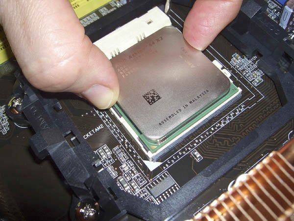 With the processor in place and seated flush with the socket, press the lever arm down and snap it into place, as shown in Figure 5-14. You may have to press the lever arm slightly away from the socket to allow it to snap into a locked position. Figure 5-14. Press the ZIF lever down until in snaps into place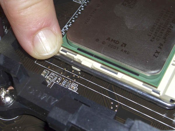
5.4.2.2. Installing the CPU coolerCurrent processors draw from 30 W to 130 W of power. Our Athlon 64 X2 4200+ processor is just below the middle of that range, so it produces about as much heat as a 60W incandescent light bulb. The processor must dissipate that heat over the surface of its heat spreader, which is about the size of a large postage stamp. Without a good CPU cooler, the processor would almost instantaneously shut itself down to prevent damage from overheating. We used the stock AMD cooler included with the retail-boxed Athlon 64 processor, which is reasonably efficient and as quiet as any but the best aftermarket coolers. If you install a third-party cooler, make absolutely certain it is rated for the exact processor model you use and follow the installation instructions included with the cooler. To install the stock AMD CPU cooler, begin by removing the plastic cover from the base of the heatsink, as shown in Figure 5-15. (We verified that it is possible to install the CPU cooler with the plastic cover still in place, but of course it won't function properly that way.) Figure 5-15. Remove the plastic cover from the heatsink base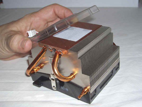 Polish the heat spreader surface on top of the processor with a paper towel or soft cloth, as shown in Figure 5-16. The goal is to remove any grease, grit, or other material that might prevent the heatsink from making intimate contact with the processor surface. Figure 5-16. Polish the CPU heat spreader to remove skin oil and other foreign material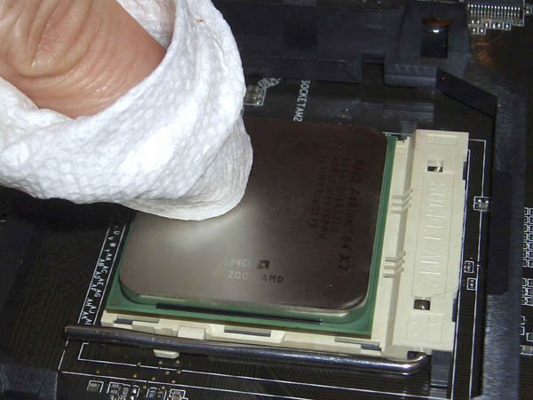 Warning: If you're using a third-party CPU cooler, also check the base of the heatsink. If the heatsink base is bare, that means it's intended to be used with thermal compound, usually called "thermal goop." In that case, also polish the heatsink base. Some heatsinks, including our stock AMD model, have a square pad made of a phase-change medium, which is a fancy term for a material that melts as the CPU heats and resolidifies as the CPU cools. This liquid/solid cycle ensures that the processor die maintains good thermal contact with the heatsink If your heatsink includes such a pad you needn't polish the base of the heatsink. (Heatsinks use either a thermal pad or thermal goop, not both.) The CPU cooler secures to the socket by two spring steel retention brackets, one on either side of the heatsink. One of those brackets floats freely, and the other is linked to a camming lever that is used to lock the CPU cooler in place.
Position the free-floating retention bracket over the plastic nub on one side of the black plastic retention module base, as shown in Figure 5-17. (The CPU cooler can be mounted in either direction. We generally connect the free-floating bracket to the side of the retention module base nearer the center of the motherboard, which is usually more cramped for space.) Figure 5-17. Position the free-floating retention bracket over the plastic nub on the retention module base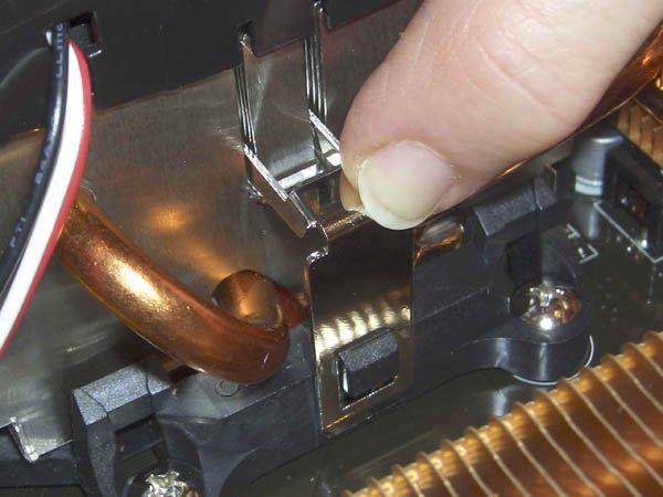 With the first retention bracket in position, make sure the cammed locking lever on the other bracket is in the fully open position shown in Figure 5-18 (rotated fully counterclockwise as you face it). Press the second bracket into position over the plastic nub on the retention module base. You may have to press down on the CPU cooler with one hand while guiding the bracket into position with the other. Figure 5-18. Position the latching retention bracket over the plastic nub on the retention module base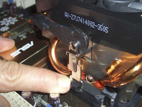 Verify that both sides of the retention bracket are in position, and then pivot the cammed locking lever fully clockwise into the locked position, as shown in Figure 5-19. It takes significant pressure to lock this lever, so be prepared to press firmly if necessary. Figure 5-19. Rotate the latching lever and press down firmly until it locks into place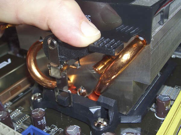 The thermal mass of the heatsink draws heat away from the CPU, but the heat must be dissipated to prevent the CPU from eventually overheating as the heatsink warms up. To dispose of excess heat as it is transferred to the heatsink, most CPU coolers, including this one, use a fan to continuously draw air through the fins of the heatsink. Some CPU fans use a drive power connector, but most are designed to attach to a dedicated CPU fan connector on the motherboard. Using a motherboard fan power connector allows the motherboard to control the CPU fan, reducing speed for quieter operation when the processor is running under light load and not generating much heat, and increasing fan speed when the processor is running under heavy load and generating more heat. The motherboard can also monitor fan speed, which allows it to send an alert to the user if the fan fails or begins running sporadically. To connect the CPU fan, locate the 4-pin header connector on the motherboard labeled CPU Fan, and plug the keyed 3-pin cable from the CPU fan into that connector, as shown in Figure 5-20. (The newer-style 4-pin CPU fan connector on the ASUS motherboard is backward compatible in pin assignments and keying with 3-pin fans.) Figure 5-20. Connect the CPU fan power lead to the CPU fan power header on the motherboard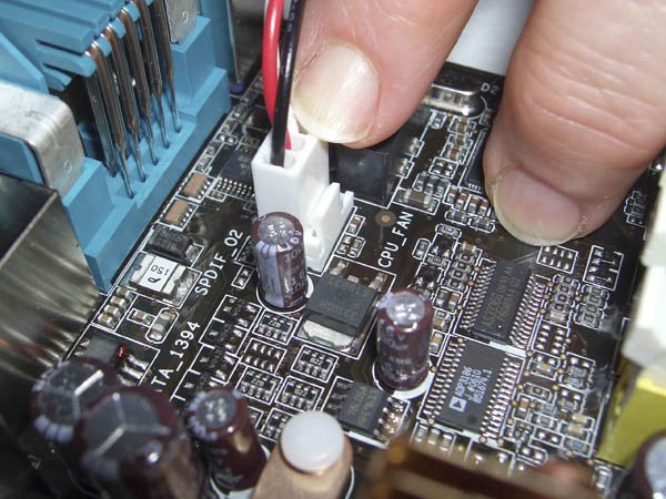 Warning: If you ever remove the CPU cooler, don't reuse the old thermal compound or pad when you reinstall it. Remove all remnants of the old thermal compound or pad, using a hair dryer or solvent if necessary, and reapply new thermal compound before you reinstall the heatsink. 5.4.2.3. Installing memoryThe Athlon 64 X2 processor includes an embedded dual-channel memory controller that provides better memory performance than a single-channel controller. You must take care when installing memory, though. The system defaults to single-channel memory operation unless you install memory modules in pairs in the proper slots. The ASUS M2N32-SLI Deluxe motherboard makes it hard to go wrong. The motherboard has four DDR2 memory slots in two color-coded pairs. If you're installing one matched pair of DIMMs, as we are, they both go in the yellow memory slots. If you add memory later, install another matched pair of DIMMs (which may differ in speed or capacity from the first pair) in the black memory slots. To install a DIMM, pivot the locking tabs on both sides of the DIMM socket outward. Align the DIMM, as shown in Figure 5-21, making sure that the keying notch in the DIMM is oriented properly with the keying tab in the slot. Figure 5-21. Align the keying notch and slide the first memory module into the slot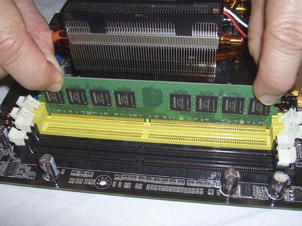 Once the DIMM is aligned and vertical relative to the slot, use both thumbs to press down firmly until the DIMM seats, as shown in Figure 5-22. When the DIMM seats, both locking tabs should automatically pivot back into the locked position, engaging the notches in the side of the DIMM. If the tabs don't fully engage the notches, press the tabs into place manually. Install the second DIMM in the other yellow slot in the same manner. Figure 5-22. Press down firmly with both thumbs until the memory module seats completely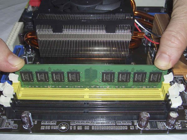 It may take significant pressure to seat a DIMM, depending on the combination of the particular modules you install and the slot. The combination of the ASUS M2N32-SLI Deluxe motherboard and the Kingston DDR2 memory modules proved to be a very tight fit. When you seat the memory modules, make certain you are pressing straight down on them. Any sideways force may damage the module or the socket. DIMMs that are difficult to seat are one reason we always install memory with the motherboard outside the case and resting on a firm, flat surface. We have seen more than one motherboard cracked when a technician who was in too much of a hurry to remove the motherboard attempted to install memory modules with the motherboard still in the case. It's very important to make absolutely sure that the memory modules are fully seated. If necessary, use a strong light and a magnifier to examine the junction between the module and the slot to verify that the module is fully and evenly seated. Partially seated memory modules can cause very subtle problems that are difficult to troubleshoot. Also, although we have never seen it ourselves, we have read credible reports of motherboards being damaged when they were powered on with a memory module only partially seated.
5.4.3. Installing the MotherboardInstalling the motherboard is the most time-consuming step in building the system because there are so many cables to connect. It's important to get all of them connected right, so take your time and verify each connection before and after you make it. 5.4.3.1. Seating and securing the motherboardTo begin, slide the motherboard into the case, as shown in Figure 5-23. Carefully align the back-panel I/O connectors with the corresponding holes in the I/O template, and slide the motherboard toward the rear of the case until the motherboard mounting holes line up with the standoffs you installed earlier. Figure 5-23. Slide the motherboard into position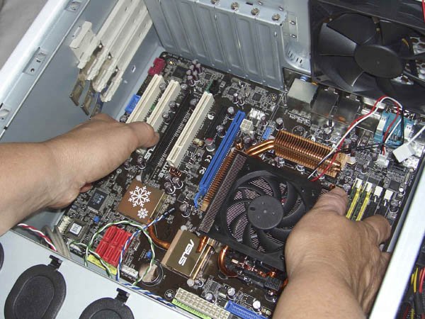 It's helpful to keep the front edge of the motherboard slightly raised as you slide the motherboard into position. As the back-panel I/O connectors on the motherboard come into contact with the back-panel I/O template, lower the front edge of the motherboard until the motherboard is level and then press gently to seat the back-panel ports in the template. In theory, at least, this prevents the metal grounding tabs on the I/O template from intruding into the ports. Before you secure the motherboard, verify that the back-panel I/O connectors mate properly with the I/O template. Make sure none of the grounding tabs intrude into a port connector. An errant tab at best blocks the port, rendering it unusable, and at worst may short out the motherboard. After you position the motherboard and verify that the back-panel I/O connectors mate cleanly with the I/O template, insert a screw through one mounting hole into the corresponding standoff. You may need to apply pressure to keep the motherboard positioned properly until you have inserted two or three screws. If you have trouble getting all the holes and standoffs aligned, insert two screws but don't tighten them completely. Use one hand to press the motherboard into alignment, with all holes matching the standoffs. Then insert one or two more screws and tighten them completely. Finish mounting the motherboard by inserting screws into all standoffs and tightening them, as shown in Figure 5-24. Figure 5-24. Install screws in all nine mounting holes to secure the motherboard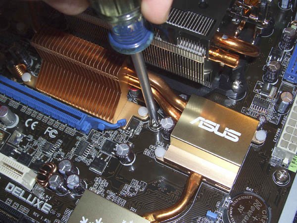
Warning: When you install motherboard mounting screws, you're also putting torque on the standoffs. Tighten the motherboard screws gently, using a standard screwdriver. When you feel tension, stop turning the driver. If you overtorque the mounting screws, you're also overtorquing the standoffs, which may strip. Don't even think about using a power screwdriver with an aluminum case. Before we installed the motherboard screws, we took a quick glance at the rear I/O panel, shown in Figure 5-25, to make sure that none of the metal ground tabs were protruding into ports. At first glance, everything looked fine, so we installed all nine motherboard screws. Figure 5-25. Everything looked fine at first glance...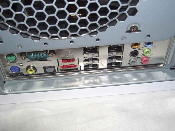 After we finished securing the motherboard, we planned to shoot an image of the rear I/O panel to show that none of the grounding tabs were obstructing ports. Ruh-roh. When we got down to shoot a close-up, we were surprised to see that both Gigabit Ethernet ports were obstructed, as shown in Figure 5-26. Although the grounding tabs weren't contacting any of the pins in the ports and so wouldn't cause a short circuit, the tabs made it impossible to connect a cable to either Ethernet port. Figure 5-26. ...but two ports were fouled by grounding tabs...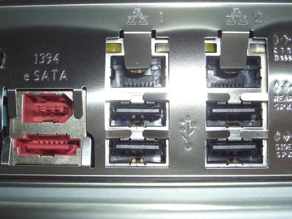 If we'd been building this system for someone else (or if we weren't on a short deadline), we'd have removed the nine motherboard screws, pulled the motherboard, and started over. But this system was for us, and we had only a few days left until deadline, so we decided to use the quick-and-dirty method shown in Figure 5-27. Barbara carefully inserted a small flat-blade screwdriver under each of the problem grounding tabs, and bent them outward to clear the ports. Figure 5-27. ...so we used a small flat-blade screwdriver carefully to bend the grounding tabs out of the way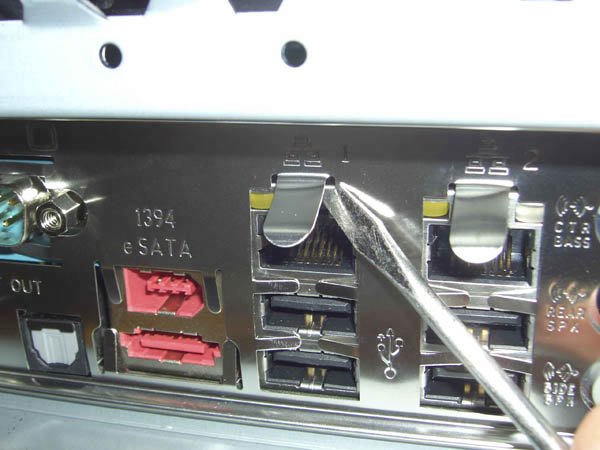 5.4.3.2. Connecting front-panel switch and indicator cablesOnce the motherboard is secured, the next step is to connect the front-panel switch and indicator cables to the motherboard. Before you begin connecting front-panel cables, examine the cables. Each is labeled descriptively, such as "Power SW" and "Reset SW" on the connector body. Match the descriptions with the front-panel connector pins on the motherboard to make sure you connect the correct cable to the appropriate pins. Figure 5-28 shows the pin assignments for the ASUS M32N32-SLI Deluxe motherboard front-panel switch/indicator connector, which is located on the left-rfront corner of the motherboard. Figure 5-28. M2N32-SLI Deluxe front-panel connector pin assignments (graphic courtesy ASUSTeK Computer, Inc.)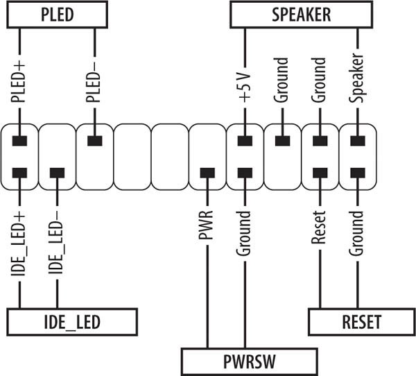
Once you determine the proper orientation for each cable, connect the power switch, reset switch, power LED, hard drive activity LED, and speaker cables, as shown in Figure 5-29. When you're connecting front panel cables, try to get it right the first time, but don't worry too much about getting it wrong. Other than the power switch cable, which must be connected properly for the system to start, none of the other front-panel switch and indicator cables is essential, and connecting them wrong won't damage the system. LED cables may or may not be polarized, but if you connect a polarized LED cable backward the worst that happens is that the LED won't light. Figure 5-29. Connect the front-panel switch and indicator cables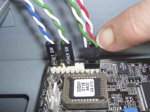
5.4.3.3. Connecting the front-panel USB portsThe Antec P150 case provides two front-panel USB ports. Both of those ports share one cable, which terminates in an Intel-standard 10-pin USB dual-port connector. The ASUS M2N32-SLI Deluxe motherboard provides three sets of USB dual-port connector pins, for a total of six USB ports in addition to the four USB ports on the back-panel I/O connector. (The motherboard we used for this system is the M2N32-SLI Deluxe Standard Edition; the M2N32-SLI Deluxe Wireless Edition has only two sets of dual USB connectors.) To enable the front-panel USB ports, locate the cable coming from the front panel that terminates in a black 10-pin 5X2 connector labeled USB. Plug that cable into either of the shrouded blue plastic USB connectors near the left-rear edge of the motherboard, as shown in Figure 5-30. The connection is keyed with a blocked hole on the cable and a missing pin on the motherboard connector, so be careful to orient the connectors properly before applying pressure. Warning: The USB and FireWire connectors on the ASUS M2N32-SLI Deluxe motherboard are shrouded and keyed. Some cases and port extender cables have oversize keyed connectors, which shrouded motherboard connectors must be large enough to accept. (If the motherboard uses bare header pins, any connector will fit as long as the pin keying is correct). Antec uses simple block connectors for its front-panel USB and FireWire cables, which means there's extra space in the shrouded motherboard connectors, as shown in Figures 5-30 and 5-32. When you connect the front-panel USB and FireWire cables, be careful to orient the cable connector correctly and not to offset the connector by one set of pins. Figure 5-30. Plug the front-panel USB cable into a motherboard USB jack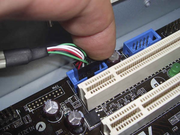
The front-panel USB ports use one of the three available sets of internal USB dual-port connectors, leaving two of those connectors free for other purposes, such as connecting a card reader or USB floppy drive. ASUS provides a dual-port USB port extender, shown in Figure 5-31, which you can use to extend one dual USB port to an expansion slot cover on the back panel. To install the port extender, simply remove an expansion slot cover and connect the cliffhanger bracket as you would a standard expansion card, then connect the cable to one of the motherboard USB connectors. Figure 5-31. The USB port extender (note blocked hole at lower left of blue connector)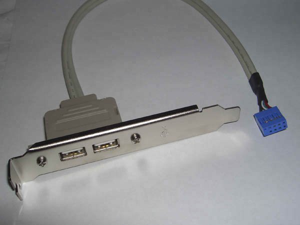 You can purchase a second USB port extender from ASUS or another supplier to reach a total of ten USB ports, eight rear and two front. We decided that the standard four rear USB ports and two front USB ports were sufficient for our purposes, so we left two of the dual-USB internal connectors free for future use. Warning: The Antec P150 case provides pin-keyed monolithic connector blocks, visible in Figure 5-31, for the front-panel USB and IEEE-1394 (FireWire) ports. The keying makes it more difficult to connect the wrong cable to a port (although it is still possible to connect a cable to the wrong connector if you accidentally offset the pins). If you are using a case that provides individual wires for the USB and/or FireWire ports, be extremely careful not to connect the USB cable to the FireWire port or vice versa. Doing so can destroy the motherboard and any connected devices. 5.4.3.4. Connecting the front-panel IEEE-1394a (FireWire) portThe Antec P150 case provides one front-panel IEEE-1394a port, with a cable that terminates in an Intel-standard 10-pin IEEE-1394a connector block. The ASUS M2N32-SLI Deluxe motherboard provides one IEEE1394a connector on the rear I/O panel and an internal FireWire connector that can be routed to the front or rear panel. To enable the front-panel FireWire port, locate the cable coming from the front panel that terminates in a black 10-pin 5X2 connector labeled IEEE-1394. Plug that cable into the shrouded red plastic IEEE-1394 connector near the left-rear edge of the motherboard, as shown in Figure 5-32. The connection is keyed with a blocked hole on the cable and a missing pin on the motherboard connector, so be careful to orient the connectors properly before applying pressure. Figure 5-32. Plug the front-panel FireWire cable into the motherboard FireWire jack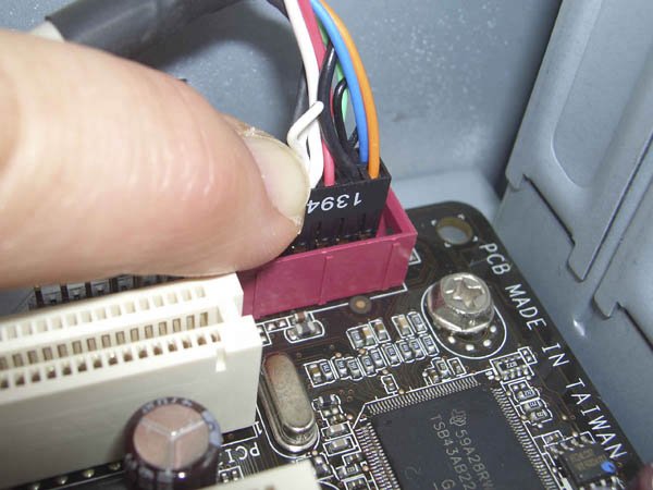 If you'd rather route the second FireWire port to the rear of the case, use the FireWire port extender that is included with the motherboard, shown in Figure 5-33. To install the port extender, remove an expansion slot cover and connect the cliffhanger bracket as you would a standard expansion card, then connect the cable to the motherboard FireWire connector. Figure 5-33. The FireWire port extender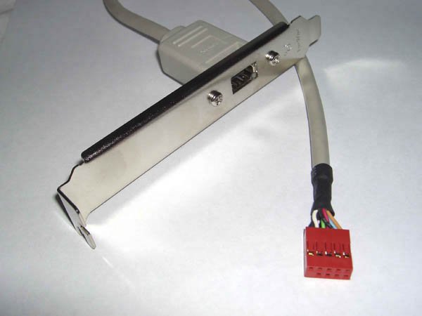 5.4.3.5. Connecting the front-panel audio portsThe Antec P150 case provides front-panel audio-in and audio-out connectors, with a cable that terminates in an Intel-standard 10-pin audio connector block. The ASUS M2N32-SLI Deluxe motherboard provides a full set of audio connectors on the back panel and an internal audio connector that can be routed to the front panel. To enable the front-panel audio ports, locate the cable coming from the front panel that terminates in a black 10-pin 5X2 connector labeled Audio. Plug that cable into the black front-panel audio connector near the center PCI expansion slot, as shown in Figure 5-34. The connection is keyed with a blocked hole on the cable and a missing pin on the motherboard connector, so be careful to orient the connectors properly before applying pressure. Figure 5-34. Plug the front-panel audio cable into the motherboard audio jack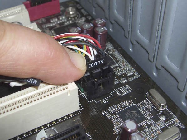
5.4.4. Installing the Optical DriveThe next step is to install the optical drive. The upper two 5.25" drive bays in the Antec P150 case include a universal drive door that conceals the front bezel of the optical drive. That means you can use any color of optical drive without the mismatch being visible. That's fortunate, because the gloss-white surface of the P150 bezel is very difficult to match with an off-the-shelf optical drive. We used a standard black optical drive for our system. To begin installing the optical drive, locate a pair of the drive rails shown in Figure 5-35. If you are installing the optical drive in one of the bays with a universal drive door, use the rear set of screw holes. If you are installing the drive in a lower bay, use the front set of screw holes. (Using the rear set recesses the drive slightly, making room for the universal drive door; using the front set puts the drive flush with the front bezel of the P150.) Figure 5-35. Install drive rails on the optical drive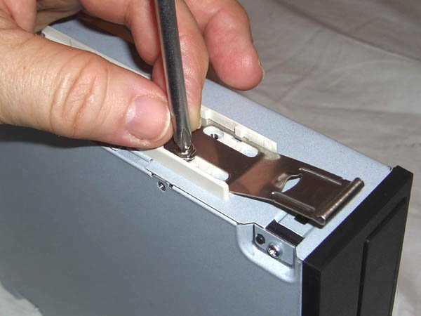 Although there are four screw holes available for each drive rail, using two screws per rail is sufficient. We generally insert the front screw in the lower hole and the rear screw in the upper hole, but any arrangement with one screw in a front hole and one in a back hole works as well. The screw holes in the drive rails are slightly oblong, providing a couple millimeters of slack. This is done to allow you to adjust the drive seating depth slightly to make sure that the pass-through button on the universal drive door can successfully operate the eject button on the actual drive bezel. We centered the screws in the screw holes, and found that they work fine with the BenQ DW1650 optical drive. If you use a different optical drive, you may have to play with the seating depth a bit to get the eject button to work properly. With the drive rails mounted, slide the drive at least partway into the bay to verify that the rails are installed properly for correct vertical alignment of the drive in the bay. The next step is to install the ATA cable. ASUS supplies an 80-wire UltraATA cable intended for use with a hard drive. Our hard drives are both Serial ATA, so we used this cable for our optical drive. (A 40-wire ATA cable is sufficient for an optical drive, but it does no harm to use the 80-wire cable.) Align the keying tab on the cable with the keying notch on the drive, and press firmly to seat the cable in the connector on the drive (Figure 5-36). If you are using an unkeyed ATA cable, make sure that pin 1 on the cable connector, indicated by a color stripe on the cable, is aligned with Pin 1 on the drive connector, which is nearly always toward the power connector on the drive. Figure 5-36. Connect the ATA cable to the optical drive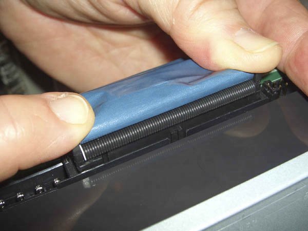 To install the drive in the case, feed the loose end of the ATA cable into the drive bay and then slide the drive partially into the bay, making sure that both drive rails are aligned with the matching slots in the case body. Place your thumbs on either side of the drive bezel and press firmly until the drive slides fully into the bay, as shown in Figure 5-37. When the drive seats, the drive rails snap into the locked position. Figure 5-37. Slide the drive into the bay and press firmly to snap the drive rails into the locked position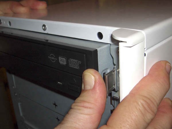 Feed the loose end of the ATA cable down toward the front edge of the motherboard. Keeping it clear of other cables will make your job easier during the final assembly steps when you neaten up the cables. Align the cable connector with the shrouded ATA connector on the motherboard, making sure that the keying tab on the cable connector is oriented properly with the keying notch on the motherboard connector. Press the ATA cable firmly into place, as shown in Figure 5-38, until it fully seats in the motherboard connector. Figure 5-38. Seat the ATA cable in the motherboard ATA connector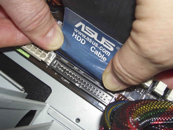
Locate the Molex power cable you installed earlier on the power supply. Again, make sure you route that cable to avoid other cables as much as possible, and then press one of the Molex connectors into the power connector on the back of the optical drive, as shown in Figure 5-39. The Molex connector is keyed with two beveled corners on one side of the connector. Those beveled edges match similar bevels on the upper side of the drive power connector. Once you're sure the connectors are aligned properly, press firmly to seat the power cable in the drive connector. Figure 5-39. Connect power to the optical drive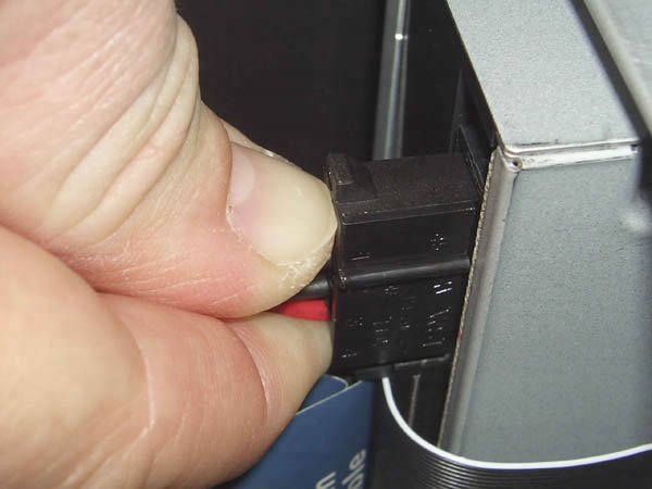 5.4.5. Connecting the ATX Power CablesOrdinarily, we connect the two ATX power cables to the motherboard as one of the final assembly steps. With this motherboard and case, it's easier to make those connections before the hard drives or video adapter is installed. The ASUS M2N32-SLI Deluxe motherboard has what we consider to be an almost ideal component layout. All of the connectors are well-placed and easily accessible, with one exception. The ATX12V supplemental power connector, shown in Figure 5-40, is so close to the blue PCI Express video card slot that it's very difficult to install the ATX12V cable with a video card already installed. Figure 5-40. Connect the ATX12V power cable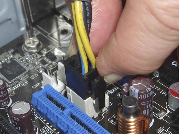 Locate the ATX12V cable, which is one of the two cables that are permanently attached to the power supply. The ATX12V cable connector and the corresponding motherboard jack are keyed using square and beveled holes. Orient the cable connector properly against the ATX12V socket, as shown in Figure 5-40, and press the cable connector firmly until it seats completely in the socket. When the cable is fully seated, the latch visible in Figure 5-40 snaps over a projection on the socket, locking the cable in place. The next step is to connect the 24-pin main ATX power cable, as shown in Figure 5-41. Align the cable connector with the socket, making sure that the latch on the cable connector is toward the front of the system. Press down firmly until the cable connector seats fully in the socket and the latch snaps into place. Make sure to complete this step before you install the hard drives, which obstruct access to the main ATX power socket. Figure 5-41. Connect the main ATX power cable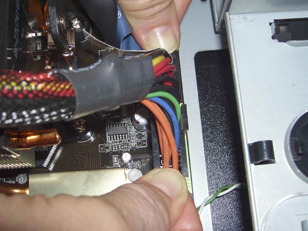 5.4.6. Installing the Hard DrivesWe're in the home stretch now. All that remains is to install the hard drives and video adapter and do a bit of cleanup. The first step in installing the hard drives is to loosen the two front-panel thumbscrews that secure the door that covers the hard drive bays, as shown in Figure 5-42. Figure 5-42. Loosen the two thumbscrews that secure the hard drive bay door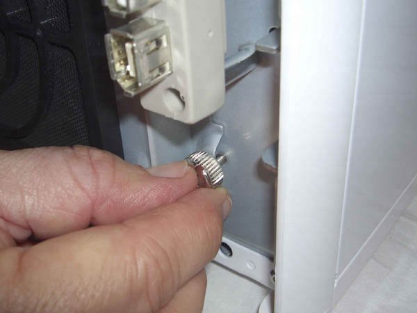 Swing the hard drive bay door open, as shown in Figure 5-43. With the door open, the mounting arrangements are clearly visible. The Antec P150 provides two methods for mounting hard drives. (Antec cautions to use one or the other, but not both.) Figure 5-43. Swing open the hard drive bay door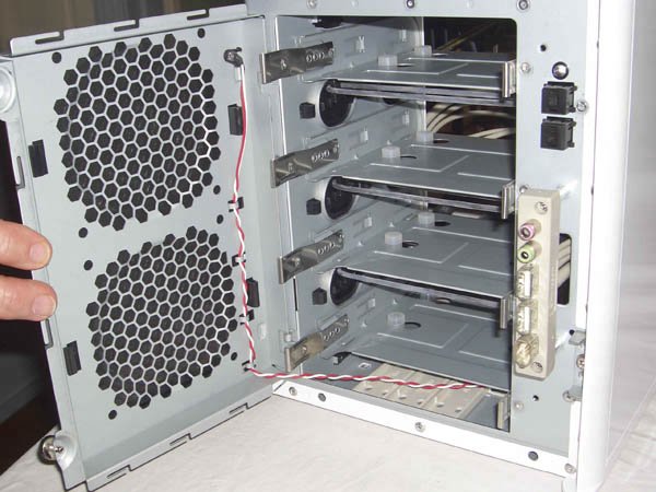 Four drive trays are visible, each secured by a pair of drive rails similar to those used to mount the optical drive. The first, and more traditional, mounting method is to secure the hard drives to those trays using screws. Antec provides soft silicone shock-mount pads, visible as the small circular white items in Figure 5-43, that isolate the drive physically from the case structure, minimizing the transfer of vibration and sound from the drive to the case. The second mounting method, popular among quiet PC enthusiasts, is to use suspension mounting. Antec provides elastic bands, visible just below the front edge of each of the top three drive trays, for those who want to use this method. (If you use suspension mounting, you can install only three hard drives instead of four.) The advantage of suspension mounting is that it is the best way to minimize hard drive noise. The disadvantage is that the hard drives are not securely connected to the case. If the system is moved, the drives may escape their mountings and rattle around inside the case, damaging the drives and other system components.
With the drive bay door open fully, lift it slightly to disengage it from its hinges and lay it flat in front of the case, as shown in Figure 5-44. Note the cable that joins the door to the case, and be careful not to put any stress on it. Figure 5-44. Remove the hard drive bay door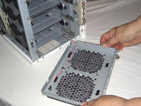
Our system will be portable, and we're not as brave as Pournelle, so we decided to screw-mount our hard drives. To begin, remove a drive tray, as shown in Figure 5-45. To do so, press inward on both drive rails to disengage the latches, and slide the hard drive tray out of the case. Figure 5-45. Remove a hard drive tray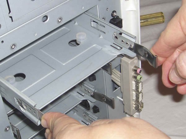 Secure the drive with four screws driven through the bottom of the drive tray and into the drive, as shown in Figure 5-46. Antec supplies special screws for this purpose, with wide heads and shafts that are only partially threaded. Place the drive upside down on the work surface, with the inverted drive tray over it. Align the screw holes and install the four screws finger-tight. Do not overtorque the mounting screws. You want them to apply some pressure to the silicone shock-mount pads, but not enough to deform them. Figure 5-46. Insert four screws to secure the drive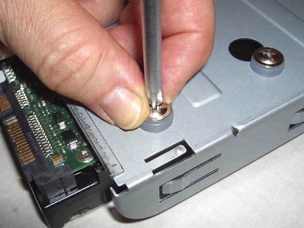 With the drive secured to the tray, slide the tray into the drive bay until it latches, as shown in Figure 5-47. It doesn't matter greatly which bays you use. We were installing only two drives in the four-drive bay, so we decided to use the top and bottom drive bays to keep the drives as far apart as possible for better air flow and cooling. Figure 5-47. Slide the mounted drive into the drive bay until it latches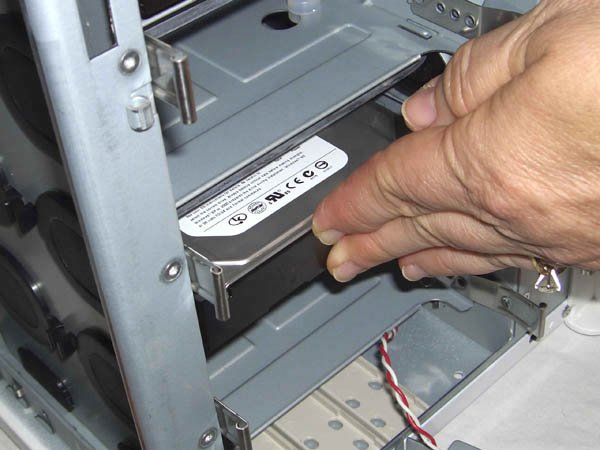 With both drives installed in the hard drive bay, reinstall the hard drive bay cover, as shown in Figure 5-48. Align the pins on the cover with the corresponding holes in the hinges on the case body, and slide the cover down into place. Then close the cover and retighten the thumbscrews, as shown in Figure 5-49. Figure 5-48. Reinstall the hard drive bay cover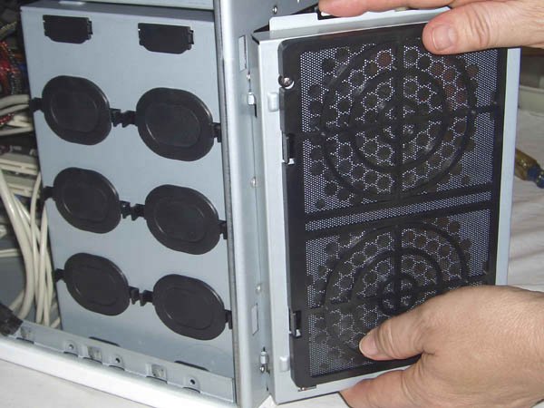 Figure 5-49. Tighten the thumbscrews to secure the hard drive bay cover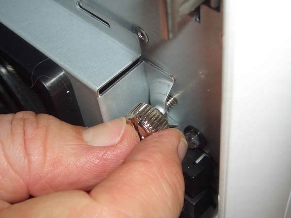
Locate the S-ATA power cable you connected to the power supply. Route that cable down to the back of the hard drives, again making sure to keep it clear of other cables to simplify things when you bundle and tie off the cables later. The S-ATA power connector uses an L-shaped connector body to ensure that it can't be connected backward. Orient the cable connector properly relative to the drive connector and then press the cable connector firmly until it slides completely onto the drive connector, as shown in Figure 5-50. Figure 5-50. Connect the S-ATA power cables to the hard drives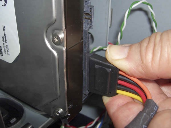
With power connected to both hard drives, the next step is to connect the data cables. Like S-ATA power cables, S-ATA data cables use an L-shaped connector body to prevent installing them backward. Align the cable connector with the drive connector, and press firmly until the cable connector slides into place, as shown in Figure 5-51. Figure 5-51. Connect the S-ATA data cables to the hard drives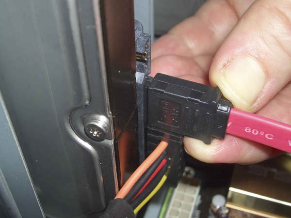 Warning: S-ATA power connectors and data connectors are quite fragile. When you insert or remove an S-ATA connector, avoid putting any sideways pressure or torque on the connector. Slide the connector straight in to insert it, and pull it straight out to remove it. Route the S-ATA data cables to the front edge of the motherboard, again avoiding entangling the cables with other cables. The ASUS M2N32-SLI Deluxe motherboard provides six S-ATA data connectors, labeled SATA-1 through SATA-6. Connect the primary hard drive to SATA-1 and the secondary drive to SATA-2, as shown in Figure 5-52. Figure 5-52. Connect the S-ATA data cables to the motherboard S-ATA interfaces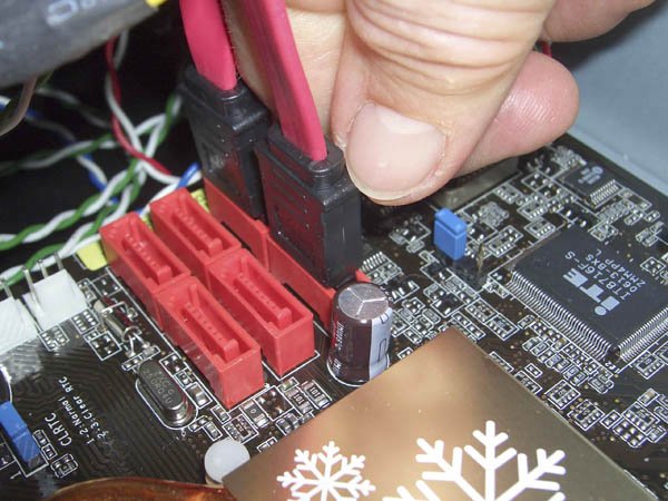 On systems with several S-ATA hard drives, we generally label both ends of each S-ATA cable to make it easier to determine which drive is connected to which interface. In this case, with only two hard drives, we didn't bother to label the cables. Our standard practice is to install the first hard drive in the top position with the secondary hard drive below it. We followed that practice here, which makes labeling the cables unnecessary.
5.4.7. Installing the Video AdapterAs an SLI motherboard, the ASUS M2N32-SLI Deluxe provides two PCI Express x16 slots for video adapters. If you're installing only one video adapter, as we are, you can install it in either slot. Warning: If you're installing two video adapters, read the motherboard and video adapter manuals carefully to learn how to configure them properly. Also remember to connect the SLI Bridge cable to the golden fingers connectors on both video adapters. An SLI Bridge cable is supplied with the motherboard, and with most SLI-capable video adapters. You can use either SLI Bridge cable. To begin installing the video adapter, temporarily slide it into position above the video adapter slot to determine which slot cover you need to remove. (We used the blue PCIe slot for our system.) Remove the screw that secures the expansion slot cover, as shown in Figure 5-53, and set it aside. Remove the slot cover and discard or store it. Figure 5-53. Remove the screw that secures the slot cover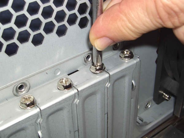 There's not much clearance once the video adapter is installed in its slot, so we recommend connecting the PCIe power cable before you install the video adapter. Not all PCI Express video adapters require supplemental power, but if yours does it's very important to remember to connect the supplemental power cable. If you forget, best case, the video adapter simply won't work. Worst case, the video adapter and motherboard may be damaged. Many older PCI Express video adapters and a few current models have a Molex (hard drive) power connector on the card. If your video adapter provides a Molex socket, connect a Molex power supply cable to it (don't use a connector labeled "fan only," as it won't supply enough power). Most PCI Express video adapters use the special 6-pin PCI Express power connector, shown in Figure 5-54. If your video adapter provides this socket, connect the PCI Express power cable you attached to the power supply earlier. Figure 5-54. Attach the PCIe power cable to the video adapter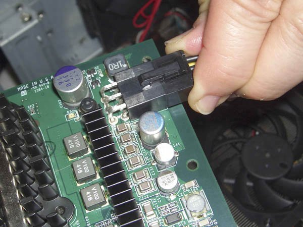 Slide the video adapter into position above the PCI Express slot, making sure the rear bracket is aligned properly with the open expansion slot cover. Once you're sure everything is properly aligned, press down on the video card with both thumbs, as shown in Figure 5-55, until the card seats firmly in the slot. Verify visually that the video card is fully seated. You may feel or hear the card snap into place, but that is no guarantee that it is fully seated. Make sure that the card is flush with the slot and level, and that the retention mechanism on the front edge of the PCIe slot is fully engaged with the matching cutout on the base of the video adapter. Figure 5-55. Align the video adapter with the slot and press firmly to seat it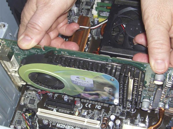 Once the video adapter is seated properly, reinsert the screw to secure the card, as shown in Figure 5-56. Make sure that tightening the screw doesn't torque the far end of the video card contacts out of the video card slot. If that happens, you may need to bend the video card bracket slightly to release the pressure that causes it to torque out of the slot. Figure 5-56. Insert the screw to secure the video adapter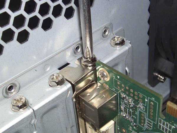 5.4.8. Finishing UpIt's all over but the shouting now. All we need to do is connect power to the rear case fan and do some tidying up of the cables. The rear case fan is an Antec 120mm TriCool, so called because it can be set to run at low, medium, or high speed. The speed control switch is a small white box at the end of a short, stiff cable. By default, the TriCool is set to run at low speed, which moves the least air but is also produces the least noise. For most systems, including this one, the low setting moves enough air to keep the system cool. Set the TriCool to medium or high speed only if the processor or motherboard temperature sensors report unacceptably high temperatures. To enable the TriCool rear case fan, connect its power lead to a standard Molex power connector, as shown in Figure 5-57. The fan draws very little current, even at high speed, so it's safe to use the same Molex cable that you use to power the optical drive or ATA hard drives. Figure 5-57. Connect power to the rear case fan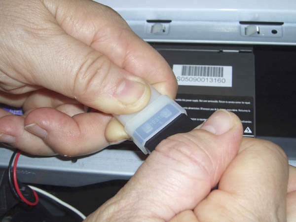 Warning: Some power supplies, including many Antec units, provide "Fan-Only" Molex connectors. If you power the TriCool fan with such a connector, we recommend setting the fan speed to high. Otherwise, the reduced voltage available on the Fan-Only Molex connector may be insufficient to start the fan spinning. The final step in building a PC is always to dress the cables, which simply means organizing, bundling, and tying them off so that they don't clutter up the case interior, impeding air flow and possibly fouling a fan. The P150 case has built-in cable organizers for just this purpose. To reveal them, remove the right side panel from the case. Gently feed the excess cable lengths through to the right side of the case and wrap them around the cable organizer hooks, as shown in Figure 5-58. Be careful not to pull too hard on the cables. Leave just a bit of slack to avoid putting undue stress on the connections. Figure 5-58. Use the cable organizer hooks to bundle and tie off excess cable lengths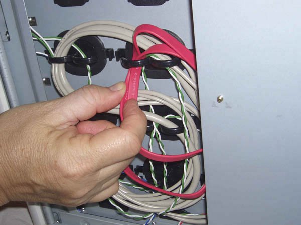
In addition to using the cable organizer, look for opportunities to tuck and bundle the ATA data cable and the cables coming from the power supply. The drive bay immediately beneath the optical drive provides a convenient niche for tucking cables into. Don't forget to dress the ATX12V cable and the rear fan power cable. Use cable ties or plastic twist-ties to secure the cable bundles to the chassis frame or other convenient tie points. Don't hesitate to disconnect cables temporarily if you need to disentangle them from other cables or to route them around parts of the case structure. Figure 5-59 shows the case interior immediately after we finished building the system. Figure 5-60 shows the case interior after we spent five minutes dressing the cables. Your goal should be a system that looks at least as well organized as Figure 5-60. Actually, because we built this system for ourselves, we spent less time dressing the cables. If we'd been building it for someone else, we'd have spent a few more minutes to make things even neater; for example, by bundling the cables visible near the front of the system and by tying off the gray front-panel cables to the frame at the upper right of the image. Figure 5-59. The case interior before dressing the cables Figure 5-60. The case interior after dressing the cables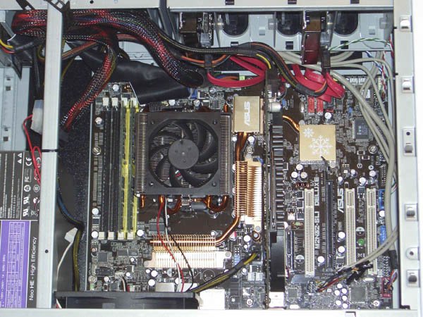 5.4.9. The Smoke TestAfter you finish building the system, take a few minutes to double-check everything. Verify that all cables are connected properly, that all drives are secured, and that there's nothing loose inside the case. Check one last time to verify the power supply is set for the correct input voltage, if applicable. It's a good idea to pick up the system and tilt it gently from side to side to make sure there are no loose screws or other items that could cause a short. Use the checklist:
Once you're certain that all is as it should be, it's time for the smoke test. Leave the cover off for now. Connect the power cable to the wall receptacle and then to the system unit. Unlike many power supplies, the Antec NeoHE 430 has a separate rocker switch on the back that controls power to the power supply. By default, it's in the "0" or off position, which means the power supply is not receiving power from the wall receptacle. Move that switch to the "1" or on position. Press the main power button on the front of the case, and the system should start up. Check to make sure that the power supply fan, CPU fan, and case fan are spinning. You should also hear the hard drive spin up and the happy beep that tells you the system is starting normally. At that point, everything should be working properly.
Once the system passes the smoke test, connect your keyboard, mouse, display, and any other external peripherals. Start the system and run BIOS Setup. Read the ASUS motherboard manual carefully, and follow the directions for initial system configuration exactly. Once you have completed BIOS Setup configuration, save your changes, shut the system down, and restart it with the operating system distribution disc in the optical drive. Install the OS, updated drivers, and your applications software, and you're ready to roll. Oh, and don't forget to replace the side panel.
|
EAN: 2147483647
Pages: 84