Future Network Considerations
Another assumption made by IPv6 transition designers is the likelihood that many upgraded hosts and routers will need to retain downward compatibility with IPv4 devices for an extended time period (possibly years or even indefinitely). It was also assumed that upgraded devices should have the option of retaining their IPv4 addressing. To accomplish these goals, IPv6 transition relies on several special functions that have been built into the IPv6 standards work, including dual-stack hosts and routers and tunneling IPv6 via IPv4. There are many proposals being studied for implementing IPv6. The three most popular are as follows:
Expanded Addressing CapabilitiesIPv6 addresses are 128-bits long and are used as identifiers for individual interfaces and sets of interfaces. All types of IPv6 addresses are assigned to interfaces, not nodes. There are three types of IPv6 addresses: unicast—identify a single interface; anycast—identify a set of interfaces such that a packet sent to an anycast address will be delivered to one member of the set; and multicast—identify a group of interfaces so that a packet sent to a multicast address is delivered to all of the interfaces in the group. With the advent of the multicast address, the broadcast addresses of IPv4 became obsolete. The leading bits in the address indicate the specific type of IPv6 address. The variable length field comprising these leading bits is called the Format Prefix (FP). Table 12-2 describes the initial allocation of those prefixes. This initial allocation supports the direct allocation of provider addresses, local use addresses, and multicast address. There is also a reserved space for NSAP and IPX addresses, and neutral-interconnect addresses. You will notice that anycast addresses are not allocated an IP. This is because the anycast addresses are allocated out of the unicast address space. Unicast addresses identify exactly one interface. They are defined as aggregatable global unicast address formats. There are many forms of unicast address format assignments in IPv6. They are broken down into the following categories:
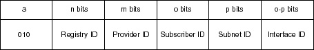
These categories organize addresses into a three-level architecture: public topology, site topology, and interface identifiers. Public Topology Public topology is a collection of providers and exchanges that provide public Internet transit services. It is divided into a set of Top Level Aggregators (TLA) and a possible hierarchy of Next Level Aggregators (NLA). 13 bits are assigned to specify the TLA and 32 bits for the NLA space. Site Topology Site topology is local to a specific site or organization that does not provide public services to nodes outside the site. Site topology is specified as a 16-bit field for Site Level Aggregators (SLA). Interface Identifiers The third level of this architecture is the Interface Identifiers. Simply put, Interface Identifiers identify interfaces on links. They must be 64 bits in length and constructed per Institute of Electrical and Electrical Engineers (IEEE) standards. Provider-Based Unicast Addresses Provider-based unicast addresses are used for global communications. Figure 12-5 shows the format for a provider-based unicast address.
The first three bits identify the address as a provider-based unicast address. The Registry ID identifies Internet address registry, which assigns provider identifier (Provider ID) to Internet Service Providers (ISPs). The ISP then assigns portions of the address space to their subscribers. The Subscriber ID distinguishes among multiple subscribers attached to the ISP identified in the Provider ID. The Subnet ID identifies a specific physical link—there can be many subnets on the same physical link. Finally, the Interface ID can identify a single interface among the group of interfaces identified by the Subnet prefix. This is similar in practice to using subnet masking to increase the size of your network. For instance, each person is given his or her address. When a mail message comes down the pike addressed to Joe Eastern, the message would first hit the ISP then “unwrap” itself to find Joe on the server.
| ||||||||||||||||||||||||||||||||||||||||||||||||||||||||||||||||||||||||||||||
EAN: 2147483647
Pages: 200
- Chapter III Two Models of Online Patronage: Why Do Consumers Shop on the Internet?
- Chapter IV How Consumers Think About Interactive Aspects of Web Advertising
- Chapter IX Extrinsic Plus Intrinsic Human Factors Influencing the Web Usage
- Chapter XVII Internet Markets and E-Loyalty
- Chapter XVIII Web Systems Design, Litigation, and Online Consumer Behavior