| Previous | Table of Contents | Next |
Chapter 2
Networking Routing Fundamentals “Achievement: Unless you try to do something beyond what you have already mastered, you will never grow.”—Successories Routing with a network, whether it is the Internet or an intranet, requires a certain amount of “common” information. This chapter provides a broad overview that covers some of the most essential points. - • Internet Protocol (IP) addressing. An overview of IP addressing methodology and understanding, subnetting, variable-length subnet masking, and classless interdomain routing is provided in this section. Why these techniques are needed will also be briefly discussed.
- • Internetwork components. This section provides an examination of the actual physical components that make use of the theories previously discussed: OSI Model, IP addresses, subnet masks, and protocols.
- • Network protocols. Basic theory on network protocols is discussed, with emphasis on understanding the difference between routed and routing protocols. Some of the fundamentals of protocol operation, with an emphasis on the evolution and operation of the Internet Protocol (IP), will be explained.
Internet Protocol (IP) Addressing This section discusses IP addressing methodology and understanding, basic subnetting, variable length subnet masking (VLSM), and classless interdomain routing (CIDR). In a properly designed and configured network, communication between hosts and servers is transparent. This is because each device using the TCP/IP protocol suite has a unique 32-bit Internet Protocol (IP) address. A device will “read” the destination IP address in the packet and make the appropriate routing decision based upon this information. In this case, a device could be either the host or server using a default gateway or a router using its routing table to forward the packet to its destination. 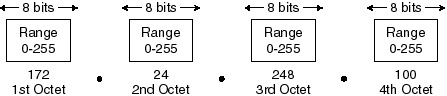
Figure 2-1 An IP address format as determined by dotted decimal notation.
IP addresses can be represented as a group of four decimal numbers, each within the range of 0 to 255. Each of these four decimal numbers will be separated by a decimal point. This method of displaying these numbers is known as dotted decimal notation. It is important to note that these numbers can also be displayed in both the binary and hexadecimal numbering systems. Figure 2-1 illustrates the basic format of an IP address as determined by using dotted decimal notation. IP addresses have only two logical components, network and host addresses, the use of which is extremely important. A network address identifies the network and must be unique; if the network is to be a part of the Internet, then it must be assigned by the Internet Network Information Center (InterNIC). A host address, on the other hand, identifies a host (device) on a network and is assigned by a local administrator. Suppose a network has been assigned an address of 172.24, for example. An administrator then assigns a host the address of 248.100. The complete address of this host is 172.24.248.100. This address is unique because only one network and one host can have this address.
Notes:
The network address component must be the same for all devices on that network, yet must be unique from all other networks. Additional information can be found in RFC 1600, which discusses reserved IP addresses.
Class A Addresses In a class A address (also known as /8), the first octet contains the network address and the other three octets make up the node address. The first bit of a class A network address must be set to 0. Although mathematically it would appear that there are 128 possible class A network addresses (remember the first is set to zero), the address 00000000 is not available, so there are only 127 such addresses. This number is further reduced because network 127.0.0.0 is reserved for loopback addressing purposes. There are only 126 class A addresses available for use. Each class A address, however, can support 126 networks that correspond to 16,777, 214 node addresses per class A address.
Notes:
Please note that the node addresses 00000000.00000000.00000000.00000000 and 11111111.11111111.11111111.11111111 are not available in ANY address class, with the example shown being a class A address. These node addresses translate into 0.0.0.0 and 255.255.255, respectively. These are typically used for protocol advertisements, such as ARP, RIP, and broadcast packets. Also note that 127.x.x.x (where x is any number between 0 and 255) is referred to as the local loopback address. A packet’s use of this address will immediately result in it being sent back to the application from which it was sent. This information can be used to assist you in troubleshooting network problems.
Class B Addresses In a class B (also known as /16) address, the network component uses the first two octets for addressing purposes. The first two bits of a class B address are always 10; that is, one and zero, not ten. The address range would then be 128.1.0.0 to 191.254.0.0. This leaves you with the first six bits of the first octet and all eight bits of the second octet, thereby providing 16,384 possible class B network addresses. The remaining octets are used to provide you with over 65,534 hosts per class B address. Class C Addresses In a class C (also known as /24) address, the first three octets are devoted to the network component. The first three bits of a class C address must be 110. The address range would then be 192.0.1.0 to 223.255.255.0. This leaves you with five bits of the first octet and eight bits of the second and third octets, thereby providing you with 2,097,152 possible class C addresses. The node address is determined by the last octet, which provides 254 nodes per network. Class D Addresses Class D addresses are special addresses that do not refer to individual networks. The first four bits of these addresses begin with 1111. The address range would then be in the range of 224 to 239. Class D addresses are used for multicast packets, which are used by many different protocols to reach multiple groups of hosts (such as ICMP router discovery or Internet Group Membership Protocol (IGMP), which is gaining in popularity since its release in IOS 11.2). Consider these addresses as “preprogrammed” within the logical structure of most network components in that when they see a destination address of this type within a packet, it triggers a response. For instance, if a host sends out the IP address 224.0.0.2, all routers (using OSPF) on its Ethernet segment respond.
| Previous | Table of Contents | Next |
|