Foundations of Networking
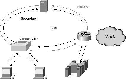
Fiber Distributed Data Internetworking (FDDI) FDDI technology is an ANSI Standard, X3T9.5, developed in the mid-1980s in order to accommodate the need for more local-area bandwidth. The standard was submitted to ISO, which created an international version of FDDI that is completely compatible with the ANSI version. FDDI operates at a speed of 100Mbps. The technology is a token passing, dual-ring LAN using fiber optic cable. The dual ring provides redundancy and reliability, with the increased operating speed over standard Ethernet, making FDDI desirable for LAN backbones and interoffice infrastructure. FDDI also uses a token passing technique in order to determine which station is allowed to insert information onto the network. The function of the second ring is for redundancy, as previously mentioned. If one of the fiber wires is broken, the ring will mend itself by wrapping back toward the portion of the fiber wires that are intact. For this reason, FDDI is highly resilient. Figure 1-10 illustrates a typical FDDI LAN.
Wide Area Networks (WANs)WANs are used to connect physically separated applications, data, and resources, thereby extending the reach of your network to form an intranet. The ideal result is seamless access to remote resources from geographically separated end users. The most common types of WAN connectivity technologies include the following:
These WAN technologies are discussed in full detail in the sections that follow. Their connectivity and protocol characteristics are also compared and contrasted. The tree shown in Figure 1-11 shows some of the basic differences and choices regarded when switching is involved.
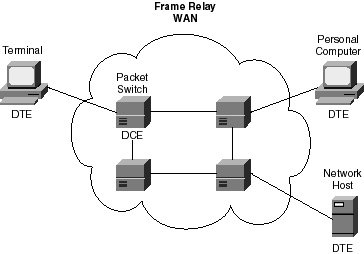
Frame Relay Frame Relay is a high performance WAN protocol that operates at the Physical and Data Link layers of the OSI reference model. Frame Relay is an example of a packet-switched technology. Frame Relay was developed in 1990 when Cisco Systems, Digital Equipment, Northern Telecom, and StrataCom formed a consortium to focus on Frame Relay technology development. This was required because initial proposals submitted during the 1980s failed to provide a complete set of standards. Since that time, ANSI and CCITT have subsequently standardized their own variation, which is now more commonly used than the original version. Packet-switched networks enable end stations to dynamically share the network media and its available bandwidth. For example, this means that two routers, a type of end station, can communicate in both directions along the circuit simultaneously. Variable length packets are used for more efficient and flexible data transfers. The advantage of this technique is that it accommodates more flexibility and a more efficient use of the available bandwidth. Devices attached to a Frame Relay WAN fall into two general categories: DTE and DCE devices, which are logical entities. That is, DTE devices initiate a communications exchange, and DCE devices respond. Descriptions and examples of DTE and DCE devices follow.
Figure 1-12 illustrates the relationship between the two different types of devices (DTE and DCE).
Frame Relay provides connection-oriented Data Link layer communication. This connection is implemented using virtual circuits. Virtual circuits provide a bi-directional communications path from one DTE device to another. A Data Link Connection Identifier (DLCI) uniquely identifies them and they become locally significant. A Permanent Virtual Circuit (PVC) is one of two types of virtual circuits used in Frame Relay implementations. PVCs are permanently established connections that are used when there is frequent and consistent data transfer between DTE devices across the Frame Relay network. Switched Virtual Circuits (SVCs) are the other types of virtual circuits used in Frame Relay implementations. SVCs are temporary connections used in situations requiring only sporadic data transfer between devices. These circuits are very similar in operation and function to ISDN (discussed later in the chapter). Frame Relay reduces network overhead by providing simple network congestion notification in the form of Forward Explicit Congestion Notification (FECN) and Backward Explicit Congestion Notification (BECN). Both types of congestion notification are controlled by a single bit within the Frame Relay packet header. This bit also contains a Discard Eligible (DE) bit that, if set, will identify less important traffic that can be discarded during periods of congestion.
|

EAN: 2147483647
Pages: 200