Graphics with GDI
|
Graphics with GDI+
The Microsoft .NET subsystem that handles graphical output is called GDI+. Graphical Device Interface (GDI) was the original Windows graphics model introduced with Microsoft Windows 3. It remained much the same through the versions of Windows that followed, but it has been greatly improved for the .NET Framework, hence the addition of the plus sign (+) to the name.
GDI+ provides a library of classes for performing simple two-dimensional graphics, such as drawing lines and simple shapes, displaying text and bitmaps, and printing. Although GDI+ is much improved compared to the original GDI, it’s still essentially a simple two-dimensional graphics library, with no advanced features such as animation or three-dimensional effects.
The System::Drawing Namespaces
The GDI+ functionality is spread across several namespaces:
-
System::Drawing provides the basic functionality.
-
System::Drawing::Drawing2D provides more advanced two-dimensional and vector graphics.
-
System::Drawing::Imaging provides functionality for image processing.
-
System::Drawing::Text provides more typographic functionality than System::Drawing.
-
System::Drawing::Printing handles printing.
-
System::Drawing::Design provides functionality for extending the design-time UI in Visual Studio .NET.
In this chapter, we’ll mainly be looking at the features offered by the basic System::Drawing namespace, as well as the printing functionality provided by System::Drawing::Printing.
The main classes in System::Drawing are listed in the following table.
| Class | Description |
|---|---|
| Bitmap | Represents a bitmap. This class can work with several common formats, including BMP, GIF, and JPG. |
| Brush | Brushes are used to fill the interiors of shapes. |
| Brushes | A collection of predefined brushes. |
| Color | Structure that represents a color. |
| Font | Represents a font. |
| FontFamily | Represents a family of fonts. |
| Graphics | Represents a drawing surface. |
| Icon | Represents an icon. |
| Image | The base for the other image classes, such as Bitmap and Metafile. |
| Pen | Used for drawing the outlines of shapes. |
| Pens | A collection of predefined pens. |
| Point, PointF | Integer and floating-point structures that represent an X,Y point. |
| Rectangle, RectangleF | Integer and floating-point structures that represent a rectangle. |
| Region | Represents a region. Regions don’t have to be rectangular. |
| Size, SizeF | Integer and floating-point structures that represent a size. |
| SolidBrush | A brush that fills a shape with a solid color. |
| StringFormat | Encapsulates a set of text layout information, such as alignment and line spacing. |
| SystemBrushes | A collection of SolidBrush objects representing the system colors. |
| SystemColors | A collection of Color objects representing the system colors. |
| SystemIcons | A collection of icons, mainly representing those used in message boxes. |
| SystemPens | A collection of Pen objects representing the system colors. |
| TextureBrush | A brush that uses an image to fill shapes. |
The Graphics Class
If you want to draw on a form, you need to consider a lot of issues first. For instance, your program might run on a Personal Digital Assistant (PDA) or a Wireless Application Protocol (WAP) phone, so is the display monochrome or color? How many colors can the display support? What’s the display resolution? And what about output to printers—they can be color or black and white, support different paper sizes and orientations, and have a range of resolutions.
However, GDI+ isolates you from worrying about these factors through the Graphics class, which represents an idealized drawing surface. As you’ll see shortly, the Graphics class supports a lot of drawing operations. You use these operations to draw, and the Graphics object renders them on the actual output device, effectively isolating you from the characteristics of the device.
| Note | If you have come across the idea of a Windows device context, you know what a Graphics object is because the Graphics class is the .NET way of encapsulating a device context. |
In addition to being the place where you send graphical output, a Graphics object can also tell you about the device it’s using. In this way, a Graphics object is an intermediary between you and the output device. The rest of this chapter will show you how to make use of the Graphics class to produce graphical output.
Creating Graphics Objects
If you look at the documentation for the Graphics class, you’ll see that it doesn’t have any constructors. You don’t create a Graphics object directly using a constructor, but instead use the Form’s CreateGraphics function to obtain one.
// Create a Graphics object Graphics* pg = myForm->CreateGraphics();
You don’t create a Graphics object directly because a Graphics object represents an underlying Windows data structure called a device context. Whether you get a new or a cached object is not your problem because using a factory method such as CreateGraphics hides the details of how the Graphics object is actually obtained.
A Graphics object uses system resources, which will be released when the object is garbage collected. Because you don’t know when that will be, it’s a good idea to free up resources when you’ve finished by calling the object’s Dispose method.
// Release the resources held by the Graphics object pg->Dispose();
It’s good programming practice to hold on to Graphics objects for as short a time as possible because the supply of graphics resources on some systems might be limited. Therefore, you should call Dispose as soon as you’ve finished with the object.
Drawing Objects
Basic drawing operations are performed using Pen and Brush objects. Pen objects are used to draw lines and the outlines of shapes, and Brush objects are used to fill the interior of shapes.
Pen Objects
Simple Pen objects are created by specifying a line width in pixels and a color.
// Create a black pen with default width of one pixel Pen* pen1 = new Pen(Color::Black); // Create a red pen two pixels wide Pen* pen2 = new Pen(Color::Red, 2.0);
The Color arguments are specified using static members of the Color structure. We’ll discuss Color in more detail later in the chapter.
If you want to create more advanced Pen objects, you can specify a Brush instead of a Color. Specifying Brush gives you the option of filling the lines with images or patterns.
Brush Objects
Brushes come in several varieties, all of which inherit from the Brush base class. The simplest is the SolidBrush, which fills an area with a solid color.
// Create a blue brush SolidBrush* br1 = new SolidBrush(Color::Blue);
The TextureBrush class uses an image to fill shapes. If the image is smaller than the shape, it can be tiled.
// Create a TextureBrush which will tile TextureBrush* br2 = new TextureBrush(new Bitmap("brush.bmp"), WrapMode::Tiled);
Standard Pens and Brushes
The Pens class has properties that define more than 140 pens representing the full range of system-defined colors. Each pen has a width of one pixel. The Brushes class does exactly the same for brushes.
// Create a one-pixel wide red pen Pen* redPen = Pens::Red; // Create a standard blue brush Brush* blueBrush = Brushes::Blue;
The SystemPens and SystemBrushes classes are very similar, but their properties reflect the standard system colors that are used to draw UI components.
// Create a pen the color of window frames Pen* redPen = SystemPens::WindowFrame; // Create a brush which has the standard color of 3D controls Brush* blueBrush = SystemBrushes::Control;
The values associated with these pens and brushes might change if the user changes the desktop color scheme through Control Panel.
Drawing Operations
Now let’s put together what you’ve learned so far and do some drawing on a form. The Graphics class has a lot of drawing methods, the most common of which are summarized in the following table.
| Method | Description |
| Clear | Fills the entire drawing area with a color |
| DrawArc | Draws an arc representing a portion of an ellipse |
| DrawBezier | Draws a Bezier curve |
| DrawClosedCurve, FillClosedCurve | Draws or fills a closed curve defined by an array of points |
| DrawCurve | Draws a curve |
| DrawEllipse, FillEllipse | Draws or fills an ellipse defined by a bounding rectangle |
| DrawIcon | Draws an icon |
| DrawImage | Draws an image |
| DrawLine | Draws a line |
| DrawLines | Draws a set of lines connecting an array of points |
| DrawPie, FillPie | Draws or fills a pie segment defined by an ellipse and two radial lines |
| DrawPolygon, FillPolygon | Draws or fills a polygon defined by an array of points |
| DrawRectangle, FillRectangle | Draws or fills a rectangle |
| DrawString | Draws a text string |
| FillRegion | Fills a region defined by a Region object |
Notice how there are separate draw and fill calls. If you want to draw a rectangle outlined in black and filled with red, you’ll have to call both DrawRectangle and FillRectangle.
The following exercise will show you how to draw some simple shapes on a form.
-
Start a new C++ Windows Forms Application (.NET) project named CppDraw.
-
Use the Properties editor to set the title of the form to Drawing.
If you examine the properties of the form, you will see that the size of the client area is set to the default value of 300 by 300 pixels.
Note The client area is that part of the form that you are responsible for maintaining and represents the area of the form inside the scroll bars and frame.
-
Drag a button from the Toolbox onto the form. Using the Properties editor, set its name to drawBtn, set its Location property to 200,200, and give it the text Draw.
Now add a handler for the Click event. You’ve seen how to add buttons and set up handlers before, but refer to Chapter 16 if you need to refresh your memory. The button is positioned toward the lower right of the window, and when it’s clicked, graphics code will execute.
-
Here’s the code for the handler:
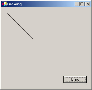
private: System::Void drawBtn_Click(System::Object * sender, System::EventArgs * e) { // Get a Graphics object Graphics* pg = CreateGraphics(); // Get a Pen Pen* pen1 = new Pen(Color::Black); // Draw a line pg->DrawLine(pen1, 20,20, 100,100); // Dispose of the Graphics object pg->Dispose(); }When the button is clicked, a Graphics object is created, along with a one-pixel-wide black pen. The DrawLine method takes a pointer to a Pen, plus the beginning and end coordinates of the line in pixels. Once the line has been drawn, you no longer need the Graphics object, so you can call its Dispose method.
Coordinates are in pixels, with (0,0) at the upper left of the form. So X coordinates increase to the right, and Y coordinates increase downward.
-
Build and run the program. You should see a line drawn on the screen when you click the button.
-
You can now add a few more calls to Graphics drawing methods. Before you do, you should add a using directive for the System:: Drawing::Drawing2D namespace at the top of the code. You’ll want this directive because some of the data structures used in the code are from this namespace. Make sure you put the following code after the first call to DrawLine in the drawBtn_Click method and before the call to Dispose.
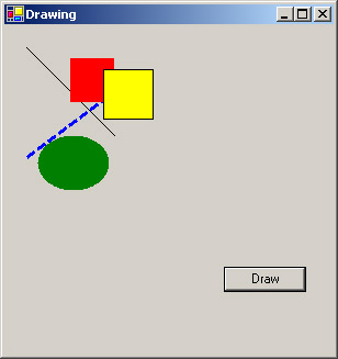
// Draw a styled line Pen* pen2 = new Pen(Color::Blue, 3.0); pen2->DashStyle = DashStyle::Dash; pg->DrawLine(pen2, 20,120, 100,60); // Draw a filled rectangle SolidBrush* sb1 = new SolidBrush(Color::Red); pg->FillRectangle(sb1, 60,30, 40,40); // Draw a filled and outlined rectangle SolidBrush* sb2 = new SolidBrush(Color::Yellow); pg->FillRectangle(sb2, 90,40, 45,45); pg->DrawRectangle(pen1, 90,40, 45,45); // Draw a filled ellipse SolidBrush* sb3 = new SolidBrush(Color::Green); pg->FillEllipse(sb3, 30,100, 65,50);
The line uses a new Pen that draws dashed lines. There are several members of the DashStyle enumeration, and you can also produce custom dashed lines by defining the dash pattern. Two rectangles are drawn, one red and one yellow, and the second one is outlined in black.
-
Build and run the application. You should get output similar to the following figure when you click the Draw button.
Paint Events
Try running the program, minimize the window to the taskbar, and bring it back by clicking the taskbar button. You’ll find that all the graphics have disappeared, and you’ll also find that the same thing happens if you let another window display on top of the Drawing application window. You can regenerate the graphics by clicking the Draw button again, but why does the drawing disappear?
What’s happening here is quite normal. Windows takes care of refreshing the components on the form—the form itself, the title bar, and the button—but it’s your responsibility to refresh anything you have drawn on the client area of the form.
Whenever a window needs to be refreshed, the operating system will send it a Paint event. If you handle these Paint events, you can ensure that the form will always display its data.
The following exercise shows you how to handle Paint events and also how to interact with the mouse. The program will capture MouseDown and MouseUp events when you click and release the mouse button, and it will draw a line between the point where you clicked the button and the point where you release it.
-
Continue with the CppDraw application from the previous exercise. You can remove the Button and handler code because you won’t be using it in this exercise, but it will do no harm to leave it in.
-
Add two Point members to the Form1 class.
Point p1, p2;
Because Point is a value type, these members are declared as variables and not as pointers.
-
The MouseDown event is fired when any mouse button is clicked down while the mouse is over a control; the MouseUp event is fired when the mouse button is released. Arrange for handler functions to be called for the MouseDown and MouseUp events on the form by using the Properties editor to add handlers for the MouseUp and MouseDown events.
Now edit the code for the MouseDown event handler so that it will save the position of the mouse pointer at the time the button was clicked.
private: System::Void Form1_MouseDown(System::Object * sender, System::Windows::Forms::MouseEventArgs * e) { p1.X = e->X; p1.Y = e->Y; }The handler functions for mouse-related events get sent MouseEventArgs objects, which contain information about the event. MouseEventArgs has several useful properties:
-
Button tells you which mouse button was clicked.
Clicks tells you the number of mouse clicks that triggered the event.
-
Delta tells you the number of notches the wheel on a wheel- equipped mouse was rotated.
-
X and Y tell you the X and Y coordinates of the mouse when the event was fired.
In this example, you’re saving the X and Y values in the variable p1.
Note Because p1 is a value type, you have to use dot notation to access its members.
The MouseUp handler is similar, in that it also stores the coordinates.
private: System::Void Form1_MouseUp(System::Object * sender, System::Windows::Forms::MouseEventArgs * e) { p2.X = e->X; p2.Y = e->Y; Graphics* gr = CreateGraphics(); Pen* pen1 = new Pen(Color::Black); gr->DrawLine(pen1, p1.X,p1.Y, p2.X,p2.Y); gr->Dispose(); }Once the coordinates have been stored, the function draws a line between the two points.
If you build and run the application at this point, you should be able to draw lines on the form using the mouse. You’ll find, however, that they disappear whenever the form needs to be repainted, just as in the previous exercise. In the rest of this exercise, you’ll save coordinates of the lines as you draw them and then redraw the collection of lines whenever the form needs to be repainted.
-
-
You’re going to store the line information in an ArrayList, which is part of the System::Collections namespace. This namespace is already referenced in Windows Forms projects, so you don’t need to add a using directive to your code. Add a private ArrayList member to the Form1 class.
ArrayList* list;
-
Create the ArrayList object in the Form1 constructor, adding the line after the call to InitializeComponent.
list = new ArrayList();
-
Add a new managed struct named Line to the top of the program, after the using directives and before the declaration of the Form1 class.
__gc struct Line { Point p1; Point p2; };This struct simply holds two Points that represent the endpoints of the line. You could easily extend this type to hold other information, such as color and line style.
-
Every time you draw a line, create a new Line object and add it to the ArrayList. Add the following code to the end of the Form1_MouseUp function, after the call to DrawLine and before the call to Dispose:
// Add a new line to the list Line* pline = new Line(); pline->p1 = p1; pline->p2 = p2; list->Add(pline);
The Line object simply holds the Points that represent the endpoints of the line.
-
Use the Properties editor to add a handler for Paint events.
-
Add the code for the Paint event handler.
private: System::Void Form1_Paint(System::Object * sender, System::Windows::Forms::PaintEventArgs * e) { Graphics* gr = e->Graphics; Pen* pen1 = new Pen(Color::Black); for(int i=0; i<list->Count; i++) { Line* pline = dynamic_cast<Line*>(list->get_Item(i)); gr->DrawLine(pen1, pline->p1.X,pline->p1.Y, pline->p2.X,pline->p2.Y); } }The function first gets a Graphics object and then creates a Pen. When you’re handling a Paint event, you get a Graphics object as part of the PaintEventArgs argument; use this one, and don’t create your own. Likewise, don’t call Dispose on this object when you finish with it; you didn’t create it, so it isn’t your responsibility to dispose of it.
The code then loops over all the items in the ArrayList, retrieving each one and casting it from an Object* back to a Line*. Once this loop is finished, you can use the coordinates in the Line object to draw the lines.
-
Build and run the program now. You’ll find that the lines you draw persist through minimizing, maximizing, and other window events that cause a repaint.
Using Color
Colors are represented by the System::Drawing::Color structure and are formed from four components: R, G, B, and A. The first three represent the proportions of red, green, and blue in the color and are specified as an integer with a value from 0 (none) to 255 (maximum). Pure red would, therefore, have a value of (255,0,0). The A value represents the transparency, or alpha value, of the color and can vary from 0 (fully transparent) to 255 (fully opaque).
Like Graphics, the Color structure doesn’t have a constructor. You create Color instances by using one of the three static factory methods:
-
FromArgb, which creates a Color from a set of alpha, red, green, and blue values
-
FromKnownColor, which creates a Color from a member of the KnownColor enumeration (discussed in a moment)
-
FromName, which creates a color given a name
The Color class defines a large number of properties that represent system- defined colors, ranging from AliceBlue to YellowGreen.
The KnownColor enumeration defines a list of system-defined colors. These colors include the standard colors defined in Color (such as AliceBlue) as well as values representing colors used in the Windows GUI, such as ActiveCaption (the color of the title bar on an active window) and WindowText (the color of the text in a window). The values of these colors might change if the user alters the desktop color scheme using Control Panel.
Here are some examples showing how to create colors:
// Pure red, fully opaque Color c1 = Color::FromArgb(255, 255, 0, 0); // The ’Cornsilk’ standard color Color c2 = Color::FromKnownColor(KnownColor::Cornsilk); // Another way to get Cornsilk Color c3 = Color::Cornsilk;
Note that once a Color has been constructed, you can’t change its values. If you need to change a Color, you’ll have to create a new Color based on the existing one.
// Pure red, fully opaque Color c4 = Color::FromArgb(255, 255, 0, 0); // Pure red, semi-transparent Color c5 = Color::FromArgb(127, c4.R, c4.G, c4.B);
The A, R, G, and B properties can be used to access the components of the Color.
Using Fonts
Two classes in System::Drawing are used to represent fonts: Font and FontFamily. A Font object represents a single font and specifies the font name, the size, and the style attributes. A FontFamily defines a set of fonts that share many characteristics but which might differ in font style.
The following table lists the major properties of the Font class. Note that they are all read-only; once created, a Font’s properties can’t be changed.
| Property | Description |
| Bold | Value is true if the font has bold style. |
| FontFamily | Gets the font family that this font belongs to. |
| Height | Gets the height of the font in the current units. |
| Italic | Value is true if the font has italic style. |
| Name | Gets the name of the font. |
| Size | Gets the size of the font in the current units. |
| SizeInPoints | Gets the size of the font in points. A point equals one seventy- second of an inch. |
| Strikeout | Value is true if the font has strikeout style. |
| Style | Gets the style information for the font. |
| Underline | Value is true if the font has underline style. |
| Unit | Gets the unit of measure for this font. By default, this will be in pixels. |
The Style is composed of one or more values from the FontStyle enumeration, which has the members Bold, Italic, Regular, Strikeout, and Underline.
The following short exercise will demonstrate how to create and use a Font to draw text on a form. You’ll enhance the existing application so that using the left button will draw lines and using the right button will draw a text string.
-
Add a Font member to the Form1 class.
private: System::Drawing::Font* font1;
You’ll need to use the fully qualified name, or the declaration will conflict with the form’s Font property.
-
Create a Font object in the Form1 constructor.
// Create the Font font1 = new System::Drawing::Font("Verdana", 8, FontStyle::Regular, GraphicsUnit::Millimeter);Once again, you need to use the fully qualified name to avoid name clashes. The first argument is the name of the font, followed by the size. What the size represents depends on the last argument, which represents the units to be used. The GraphicsUnit enumeration contains all the valid units, which can be any of the following:
-
Display, which uses one seventy-fifth of an inch as the unit of measure
-
Document, which uses document units (one three-hundredth of an inch)
-
Inch
-
Millimeter
-
Pixel
-
Point, which uses printer’s points (one seventy-second of an inch)
-
World, which uses world coordinates
In this case, I’m specifying 8 millimeters, which will be easily visible on the form. The font style can be any of the values from the FontStyle enumeration, combined with the bitwise OR operator (|) if you want to use more than one of them.
-
-
Edit the Form1_MouseUp function so that it differentiates between the left and right mouse buttons.
private: System::Void Form1_MouseUp(System::Object * sender, System::Windows::Forms::MouseEventArgs * e) { Graphics* gr = CreateGraphics(); Pen* pen1 = new Pen(Color::Black); if (e->Button == MouseButtons::Left) { // Draw lines p2.X = e->X; p2.Y = e->Y; gr->DrawLine(pen1, p1.X,p1.Y, p2.X,p2.Y); // Add a new line to the list Line* pl = new Line(); pl->p1 = p1; pl->p2 = p2; list->Add(pl); } else if (e->Button == MouseButtons::Right) { // Draw text gr->DrawString(S"text", font1, Brushes::Black, e->X, e->Y); } gr->Dispose(); }The function now checks which mouse button gave rise to the event. If it’s the left button, a line gets drawn. If it’s the right button, a string is drawn at the mouse position using the font you just created. The third argument to DrawString is a Brush, which defines the fill color or pattern for the text.
-
Build and run the application. You should be able to draw lines and text using the left and right mouse buttons.
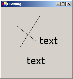
Note that the text isn’t persistent. Unlike the lines, it will disappear when the window gets repainted.
|
EAN: N/A
Pages: 208