Section 5.6. Overview of the MINIX 3 File System
5.6. Overview of the MINIX 3 File SystemLike any file system, the MINIX 3 file system must deal with all the issues we have just studied. It must allocate and deallocate space for files, keep track of disk blocks and free space, provide some way to protect files against unauthorized usage, and so on. In the remainder of this chapter we will look closely at MINIX 3 to see how it accomplishes these goals. In the first part of this chapter, we have repeatedly referred to UNIX rather than to MINIX 3 for the sake of generality, although the external interfaces of the two is virtually identical. Now we will concentrate on the internal design of MINIX 3. For information about the UNIX internals, see Thompson (1978), Bach (1987), Lions (1996), and Vahalia (1996). The MINIX 3 file system is just a big C program that runs in user space (see Fig. 2-29). To read and write files, user processes send messages to the file system telling what they want done. The file system does the work and then sends back a reply. The file system is, in fact, a network file server that happens to be running on the same machine as the caller. This design has some important implications. For one thing, the file system can be modified, experimented with, and tested almost completely independently of the rest of MINIX 3. For another, it is very easy to move the file system to any computer that has a C compiler, compile it there, and use it as a free-standing UNIX-like remote file server. The only changes that need to be made are in the area of how messages are sent and received, which differs from system to system. In the following sections, we will present an overview of many of the key areas of the file system design. Specifically, we will look at messages, the file system layout, the bitmaps, i-nodes, the block cache, directories and paths, file descriptors, file locking, and special files (plus pipes). After studying these topics, we will show a simple example of how the pieces fit together by tracing what happens when a user process executes the read system call. 5.6.1. MessagesThe file system accepts 39 types of messages requesting work. All but two are for MINIX 3 system calls. The two exceptions are messages generated by other parts of MINIX 3. Of the system calls, 31 are accepted from user processes. Six system call messages are for system calls which are handled first by the process manager, which then calls the file system to do a part of the work. Two other messages are also handled by the file system. The messages are shown in Fig. 5-33.
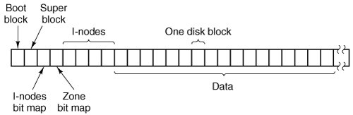
The structure of the file system is basically the same as that of the process manager and all the I/O device drivers. It has a main loop that waits for a message to arrive. When a message arrives, its type is extracted and used as an index into a table containing pointers to the procedures within the file system that handle all the types. Then the appropriate procedure is called, it does its work and returns a status value. The file system then sends a reply back to the caller and goes back to the top of the loop to wait for the next message. 5.6.2. File System LayoutA MINIX 3 file system is a logical, self-contained entity with i-nodes, directories, and data blocks. It can be stored on any block device, such as a floppy disk or a hard disk partition. In all cases, the layout of the file system has the same structure. Figure 5-34 shows this layout for a floppy disk or a small hard disk partition with 64 i-nodes and a 1-KB block size. In this simple example, the zone bitmap is just one 1-KB block, so it can keep track of no more than 8192 1-KB zones (blocks), thus limiting the file system to 8 MB. Even for a floppy disk, only 64 i-nodes puts a severe limit on the number of files, so rather than the four blocks reserved for i-nodes in the figure, more would probably be used. Reserving eight blocks for i-nodes would be more practical but our diagram would not look as nice. For a modern hard disk, both the i-node and zone bitmaps will be much larger than 1 block, of course. The relative size of the various components in Fig. 5-34 may vary from file system to file system, depending on their sizes, how many files are allowed maximum, and so on. But all the components are always present and in the same order. Figure 5-34. Disk layout for a floppy disk or small hard disk partition, with 64 i-nodes and a 1-KB block size (i.e., two consecutive 512-byte sectors are treated as a single block). |

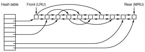
1. | Whether to put the block on the front or rear of the LRU list. |
2. | Whether to write the block (if modified) to disk immediately or not. |
Almost all blocks go on the rear of the list in true LRU fashion. The exception is blocks from the RAM disk; since they are already in memory there is little advantage to keeping them in the block cache.
A modified block is not rewritten until either one of two events occurs:
1. | It reaches the front of the LRU chain and is evicted. |
2. | A sync system call is executed. |
Sync does not traverse the LRU chain but instead indexes through the array of buffers in the cache. Even if a buffer has not been released yet, if it has been modified, sync will find it and ensure that the copy on disk is updated.
Policies like this invite tinkering. In an older version of MINIX a superblock was modified when a file system was mounted, and was always rewritten immediately to reduce the chance of corrupting the file system in the event of a crash. Superblocks are modified only if the size of a RAM disk must be adjusted at startup time because the RAM disk was created bigger than the RAM image device. However, the superblock is not read or written as a normal block, because it is always 1024 bytes in size, like the boot block, regardless of the block size used for blocks handled by the cache. Another abandoned experiment is that in older versions of MINIX there was a ROBUST macro definable in the system configuration file, include/minix/config.h, which, if defined, caused the file system to mark i-node, directory, indirect, and bit-map blocks to be written immediately upon release. This was intended to make the file system more robust; the price paid was slower operation. It turned out this was not effective. A power failure occurring when all blocks have not been yet been written is going to cause a headache whether it is an i-node or a data block that is lost.
Note that the header flag indicating that a block has been modified is set by the procedure within the file system that requested and used the block. The procedures get_block and put_block are concerned just with manipulating the linked lists. They have no idea which file system procedure wants which block or why.
5.6.6. Directories and Paths
Another important subsystem within the file system manages directories and path names. Many system calls, such as open, have a file name as a parameter. What is really needed is the i-node for that file, so it is up to the file system to look up the file in the directory tree and locate its i-node.
A MINIX directory is a file that in previous versions contained 16-byte entries, 2 bytes for an i-node number and 14 bytes for the file name. This design limited disk partitions to 64-KB files and file names to 14 characters, the same as V7 UNIX. As disks have grown file names have also grown. In MINIX 3 the V3 file system provides 64 bytes directory entries, with 4 bytes for the i-node number and 60 bytes for the file name. Having up to 4 billion files per disk partition is effectively infinite and any programmer choosing a file name longer than 60 characters should be sent back to programming school.
Note that paths such as
/usr/ast/course_material_for_this_year/operating_systems/examination-1.ps
are not limited to 60 charactersjust the individual component names. The use of fixed-length directory entries, in this case, 64 bytes, is an example of a tradeoff involving simplicity, speed, and storage. Other operating systems typically organize directories as a heap, with a fixed header for each file pointing to a name on the heap at the end of the directory. The MINIX 3 scheme is very simple and required practically no code changes from V2. It is also very fast for both looking up names and storing new ones, since no heap management is ever required. The price paid is wasted disk storage, because most files are much shorter than 60 characters.
It is our firm belief that optimizing to save disk storage (and some RAM storage since directories are occasionally in memory) is the wrong choice. Code simplicity and correctness should come first and speed should come second. With modern disks usually exceeding 100 GB, saving a small amount of disk space at the price of more complicated and slower code is generally not a good idea. Unfortunately, many programmers grew up in an era of tiny disks and even tinier RAMs, and were trained from day 1 to resolve all trade-offs between code complexity, speed, and space in favor of minimizing space requirements. This implicit assumption really has to be reexamined in light of current realities.
Now let us see how the path /usr/ast/mbox/ is looked up. The system first looks up usr in the root directory, then it looks up ast in /usr/, and finally it looks up mbox in /usr/ast/. The actual lookup proceeds one path component at a time, as illustrated in Fig. 5-16.
The only complication is what happens when a mounted file system is encountered. The usual configuration for MINIX 3 and many other UNIX-like systems is to have a small root file system containing the files needed to start the system and to do basic system maintenance, and to have the majority of the files, including users' directories, on a separate device mounted on /usr. This is a good time to look at how mounting is done. When the user types the command
mount /dev/c0d1p2 /usr
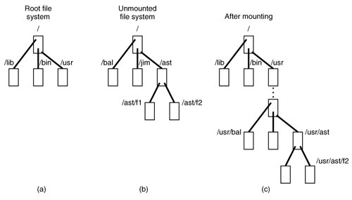
on the terminal, the file system contained on hard disk 1, partition 2 is mounted on top of /usr/ in the root file system. The file systems before and after mounting are shown in Fig. 5-38.
Figure 5-38. (a) Root file system. (b) An unmounted file system. (c) The result of mounting the file system of (b) on /usr/. (This item is displayed on page 561 in the print version)
The key to the whole mount business is a flag set in the memory copy of the i-node of /usr after a successful mount. This flag indicates that the i-node is mounted on. The mount call also loads the super-block for the newly mounted file system into the super_block table and sets two pointers in it. Furthermore, it puts the root i-node of the mounted file system in the inode table.
In Fig. 5-35 we see that super-blocks in memory contain two fields related to mounted file systems. The first of these, the i-node-for-root-of-mounted-file-system, is set to point to the root i-node of the newly mounted file system. The second, the i-node-mounted-upon, is set to point to the i-node mounted on, in this case, the i-node for /usr. These two pointers serve to connect the mounted file system to the root and represent the "glue" that holds the mounted file system to the root [shown as the dots in Fig. 5-38(c)]. This glue is what makes mounted file systems work.
When a path such as /usr/ast/f2 is being looked up, the file system will see a flag in the i-node for /usr/ and realize that it must continue searching at the root inode of the file system mounted on /usr/. The question is: "How does it find this root i-node?"
The answer is straightforward. The system searches all the superblocks in memory until it finds the one whose i-node mounted on field points to /usr/. This must be the superblock for the file system mounted on /usr/. Once it has the superblock, it is easy to follow the other pointer to find the root i-node for the mounted file system. Now the file system can continue searching. In this example, it looks for ast in the root directory of hard disk partition 2.
5.6.7. File Descriptors
Once a file has been opened, a file descriptor is returned to the user process for use in subsequent read and write calls. In this section we will look at how file descriptors are managed within the file system.
Like the kernel and the process manager, the file system maintains part of the process table within its address space. Three of its fields are of particular interest. The first two are pointers to the i-nodes for the root directory and the working directory. Path searches, such as that of Fig. 5-16, always begin at one or the other, depending on whether the path is absolute or relative. These pointers are changed by the chroot and chdir system calls to point to the new root or new working directory, respectively.
The third interesting field in the process table is an array indexed by file descripttor number. It is used to locate the proper file when a file descriptor is presented. At first glance, it might seem sufficient to have the k-th entry in this array just point to the i-node for the file belonging to file descriptor k. After all, the i-node is fetched into memory when the file is opened and kept there until it is closed, so it is sure to be available.
Unfortunately, this simple plan fails because files can be shared in subtle ways in MINIX 3 (as well as in UNIX). The trouble arises because associated with each file is a 32-bit number that indicates the next byte to be read or written. It is this number, called the file position, that is changed by the lseek system call. The problem can be stated easily: "Where should the file pointer be stored?"
The first possibility is to put it in the i-node. Unfortunately, if two or more processes have the same file open at the same time, they must all have their own file pointers, since it would hardly do to have an lseek by one process affect the next read of a different process. Conclusion: the file position cannot go in the inode.
What about putting it in the process table? Why not have a second array, paralleling the file descriptor array, giving the current position of each file? This idea does not work either, but the reasoning is more subtle. Basically, the trouble comes from the semantics of the fork system call. When a process forks, both the parent and the child are required to share a single pointer giving the current position of each open file.
To better understand the problem, consider the case of a shell script whose output has been redirected to a file. When the shell forks off the first program, its file position for standard output is 0. This position is then inherited by the child, which writes, say, 1 KB of output. When the child terminates, the shared file position must now be 1024.
Now the shell reads some more of the shell script and forks off another child. It is essential that the second child inherit a file position of 1024 from the shell, so it will begin writing at the place where the first program left off. If the shell did not share the file position with its children, the second program would overwrite the output from the first one, instead of appending to it.
As a result, it is not possible to put the file position in the process table. It really must be shared. The solution used in UNIX and MINIX 3 is to introduce a new, shared table, filp, which contains all the file positions. Its use is illustrated in Fig. 5-39. By having the file position truly shared, the semantics of fork can be implemented correctly, and shell scripts work properly.
Figure 5-39. How file positions are shared between a parent and a child. (This item is displayed on page 563 in the print version)
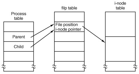
Although the only thing that the filp table really must contain is the shared file position, it is convenient to put the i-node pointer there, too. In this way, all that the file descriptor array in the process table contains is a pointer to a filp entry. The filp entry also contains the file mode (permission bits), some flags indicating whether the file was opened in a special mode, and a count of the number of processes using it, so the file system can tell when the last process using the entry has terminated, in order to reclaim the slot.
5.6.8. File Locking
Yet another aspect of file system management requires a special table. This is file locking. MINIX 3 supports the POSIX interprocess communication mechanism of advisory file locking. This permits any part, or multiple parts, of a file to be marked as locked. The operating system does not enforce locking, but processes are expected to be well behaved and to look for locks on a file before doing anything that would conflict with another process.
The reasons for providing a separate table for locks are similar to the justifications for the filp table discussed in the previous section. A single process can have more than one lock active, and different parts of a file may be locked by more than one process (although, of course, the locks cannot overlap), so neither the process table nor the filp table is a good place to record locks. Since a file may have more than one lock placed upon it, the i-node is not a good place either.
MINIX 3 uses another table, the file_lock table, to record all locks. Each slot in this table has space for a lock type, indicating if the file is locked for reading or writing, the process ID holding the lock, a pointer to the i-node of the locked file, and the offsets of the first and last bytes of the locked region.
5.6.9. Pipes and Special Files
Pipes and special files differ from ordinary files in an important way. When a process tries to read or write a block of data from a disk file, it is almost certain that the operation will complete within a few hundred milliseconds at most. In the worst case, two or three disk accesses might be needed, not more. When reading from a pipe, the situation is different: if the pipe is empty, the reader will have to wait until some other process puts data in the pipe, which might take hours. Similarly, when reading from a terminal, a process will have to wait until somebody types something.
As a consequence, the file system's normal rule of handling a request until it is finished does not work. It is necessary to suspend these requests and restart them later. When a process tries to read or write from a pipe, the file system can check the state of the pipe immediately to see if the operation can be completed. If it can be, it is, but if it cannot be, the file system records the parameters of the system call in the process table, so it can restart the process when the time comes.
Note that the file system need not take any action to have the caller suspended. All it has to do is refrain from sending a reply, leaving the caller blocked waiting for the reply. Thus, after suspending a process, the file system goes back to its main loop to wait for the next system call. As soon as another process modifies the pipe's state so that the suspended process can complete, the file system sets a flag so that next time through the main loop it extracts the suspended process' parameters from the process table and executes the call.
The situation with terminals and other character special files is slightly different. The i-node for each special file contains two numbers, the major device and the minor device. The major device number indicates the device class (e.g., RAM disk, floppy disk, hard disk, terminal). It is used as an index into a file system table that maps it onto the number of the corresponding I/O device driver. In effect, the major device determines which I/O driver to call. The minor device number is passed to the driver as a parameter. It specifies which device is to be used, for example, terminal 2 or drive 1.
In some cases, most notably terminal devices, the minor device number encodes some information about a category of devices handled by a driver. For instance, the primary MINIX 3 console, /dev/console, is device 4, 0 (major, minor). Virtual consoles are handled by the same part of the driver software. These are devices /dev/ttyc1 (4,1), /dev/ttyc2 (4,2), and so on. Serial line terminals need different low-level software, and these devices, /dev/tty00, and /dev/tty01 are assigned device numbers 4, 16 and 4, 17. Similarly, network terminals use pseudo-terminal drivers, and these also need different low-level software. In MINIX 3 these devices, ttyp0, ttyp1, etc., are assigned device numbers such as 4, 128 and 4, 129. These pseudo devices each have an associated device, ptyp0, ptyp1, etc. The major, minor device number pairs for these are 4,192 and 4,193, etc. These numbers are chosen to make it easy for the device driver to call the low-level functions required for each group of devices. It is not expected that anyone is going to equip a MINIX 3 system with 192 or more terminals.
When a process reads from a special file, the file system extracts the major and minor device numbers from the file's i-node, and uses the major device number as an index into a file system table to map it onto the process number of the corresponding device driver. Once it has identified the driver, the file system sends it a message, including as parameters the minor device, the operation to be performed, the caller's process number and buffer address, and the number of bytes to be transferred. The format is the same as in Fig. 3-15, except that POSITION is not used.
If the driver is able to carry out the work immediately (e.g., a line of input has already been typed on the terminal), it copies the data from its own internal buffers to the user and sends the file system a reply message saying that the work is done. The file system then sends a reply message to the user, and the call is finished. Note that the driver does not copy the data to the file system. Data from block devices go through the block cache, but data from character special files do not.
On the other hand, if the driver is not able to carry out the work, it records the message parameters in its internal tables, and immediately sends a reply to the file system saying that the call could not be completed. At this point, the file system is in the same situation as having discovered that someone is trying to read from an empty pipe. It records the fact that the process is suspended and waits for the next message.
When the driver has acquired enough data to complete the call, it transfers them to the buffer of the still-blocked user and then sends the file system a message reporting what it has done. All the file system has to do is send a reply message to the user to unblock it and report the number of bytes transferred.
5.6.10. An Example: The READ System Call
As we shall see shortly, most of the code of the file system is devoted to carrying out system calls. Therefore, it is appropriate that we conclude this overview with a brief sketch of how the most important call, read, works.
When a user program executes the statement
n = read(fd, buffer, nbytes);
to read an ordinary file, the library procedure read is called with three parameters. It builds a message containing these parameters, along with the code for read as the message type, sends the message to the file system, and blocks waiting for the reply. When the message arrives, the file system uses the message type as an index into its tables to call the procedure that handles reading.
This procedure extracts the file descriptor from the message and uses it to locate the filp entry and then the i-node for the file to be read (see Fig. 5-39). The request is then broken up into pieces such that each piece fits within a block. For example, if the current file position is 600 and 1024 bytes have been requested, the request is split into two parts, for 600 to 1023, and for 1024 to 1623 (assuming 1-KB blocks).
For each of these pieces in turn, a check is made to see if the relevant block is in the cache. If the block is not present, the file system picks the least recently used buffer not currently in use and claims it, sending a message to the disk device driver to rewrite it if it is dirty. Then the disk driver is asked to fetch the block to be read.
Once the block is in the cache, the file system sends a message to the system task asking it to copy the data to the appropriate place in the user's buffer (i.e., bytes 600 to 1023 to the start of the buffer, and bytes 1024 to 1623 to offset 424 within the buffer). After the copy has been done, the file system sends a reply message to the user specifying how many bytes have been copied.
When the reply comes back to the user, the library function read extracts the reply code and returns it as the function value to the caller.
One extra step is not really part of the read call itself. After the file system completes a read and sends a reply, it initiates reading additional blocks, provided that the read is from a block device and certain other conditions are met. Since sequential file reads are common, it is reasonable to expect that the next blocks in a file will be requested in the next read request, and this makes it likely that the desired block will already be in the cache when it is needed. The number of blocks requested depends upon the size of the block cache; as many as 32 additional blocks may be requested. The device driver does not necessarily return this many blocks, and if at least one block is returned a request is considered successful.
EAN: 2147483647
Pages: 102