19.4 The Coup de Grace: Using Attribute Information in Bills of Materials, Spreadsheets, or Database Programs
|
| < Day Day Up > |
|
This nifty trick is guaranteed to move you to the head of the class!
One of the most useful and timesaving devices available to AutoCAD users lies in AutoCAD's ability to save steps along the road to project completion. In this section of our lesson, we'll discover how to use the information we've attached to our blocks. We'll create a text file containing information acquired from our blocks. We'll use this text file to create a bill of materials on our drawing. We'll also create a spreadsheet for use in Microsoft Excel.
19.4.1 Setting Up the Attribute Extraction Template File
Before extracting information from your blocks, you must first tell AutoCAD exactly what information you wish to extract. To do this, you must create a template file. A template file is a text file that defines the information you want, from where it'll come, whether the information is in number or character format, and how many spaces to allow for the information in the destination file.
It isn't as complicated as it sounds. Information in a block comes in two forms - user-supplied data and AutoCAD-supplied data.
-
User supplied data is any information you identified when creating the attribute or inserting the block. This includes all attribute values. Identify the attribute by its tag.
-
AutoCAD-supplied data includes all the other information stored in AutoCAD's database and related to the block. You identify the information with a tag assigned by AutoCAD. This includes the following data:
-
Name of the block
-
The Handle of the block (the block's identifier in AutoCAD's database)
-
X insertion coordinate
-
Y insertion coordinate
-
Z insertion coordinate
-
X scale factor of the block
-
Y scale factor of the block
-
Z scale factor of the block
-
Layer on which the block was inserted
-
The Orientation of the block
AutoCAD-supplied data also includes a Number option that counts, or numbers, the block data in the extraction file.
(Refer to Figures 19.4.1a and 19.4.1b for the following explanation.)
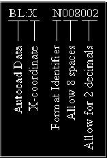
Figure 19.4.1a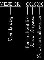
Figure 19.4.1b -
-
AutoCAD-supplied data is preceded by a BL: in the template file. User-supplied data is not.
-
In the template file, you must identify the format of the information you're asking AutoCAD to find as either character (C) or numerical (N). Numerical information can contain only numbers - no $, %, #, or * symbols. All other formats are considered character.
-
Following the format identifier, tell AutoCAD how many spaces in the extraction file to allow for this information. Give this as a three-digit number.
-
Use the second set of three digits to tell AutoCAD how many decimal places to allow for a numerical value.
A sample file for the pid-19 drawing might look like this:
| BL:Name | C010000 |
|---|---|
| BL:X | N008002 |
| BL:Y | N008002 |
| BLANK | C005000 |
| TYPE | C010000 |
| SIZE | C005000 |
| RATING | C007000 |
| VENDOR | C010000 |
| PRICE | C010000 |
(The BLANK tag will cause a space to appear between the AutoCAD-supplied information and the user data.)
Let's create a template file for our PID drawing.
| Note | A crucial (and frustrating) note: You must follow the last entry in the template file with a carriage return (enter) but only a single carriage return. AutoCAD is completely unforgiving about this. Without the return, the last tag won't be recognized; more than a single return will cause an Invalid field specification error. |
Do This: 19.4.1.1 Create an Attribute Extraction Template File
-
Open the Windows Notepad program. (Use the Notepad command at AutoCAD's command prompt.)
-
Type this code:
BL:NAME C010000
BLANK C005000
TYPE C015000
SIZE C005000
RATING C007000
VENDOR C010000
PRICE N010002 -
Save the file as MyPID to the C:\Steps\Lesson19 folder (Notepad will automatically add the .txt extension).
-
Close the Notepad window.
19.4.2 Extracting the Data
You'll find it easy to extract block data. The command is Attext; AutoCAD displays the Attribute Extraction dialog box shown in Figure 19.4.2a. As with most of AutoCAD's dialog boxes, we've a few frames of information to provide.
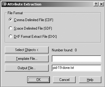
Figure 19.4.2a
-
The options provided in the first frame allow you to determine the format of the extraction file.
-
The default - Comma Delimited File (CDF) - simply means that commas will separate the data in the destination file. Database programs, such as MS Access of DBase, readily recognize this format.
-
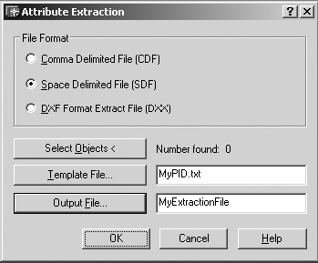
A Space Delimited File (SDF) separates the data in the destination file with spaces. This is the easiest format for the novice to understand and the format in which you'll create an extraction file for our bill of materials.
-
A DXF file is designed for programmer use or to transfer information between CAD programs (such as AutoCAD and Microstation). We'll ignore it here.
-
-
The Select Objects< button allows you to select the objects to include in the extraction. If you ignore this option, the extraction file will automatically include all the blocks in the drawing.
-
The Template File… button presents the standard Open File dialog box for you to select the template file (the file you created in our last exercise). Alternately, you can enter the file name (and path) into the text box next to the button.
-
The Output File… button also presents the standard Open File dialog box for you to select the destination file for the extraction. Alternately, you can enter a file name (and path) into the text box for a new file.
Let's extract some data.
| Note | You can use a command line approach to the Attext command by placing the standard dash in front of the command, but the prompts are the same and the dialog box is easier to use. Still, feel free to experiment with it if you're more keyboard oriented. |
Do This: 19.4.2.1 Extracting Attribute Data
-
Be sure you're still in the pid-19-done.dwg file the C:\Steps\Lesson19 folder. If not, please open it now.
-
Follow these steps.
TOOLS
COMMAND SEQUENCE
STEPS

Command: z
1. Zoom out (Zoom All) so you can see the entire drawing.
No Button Available
Command: attext
2. Enter the Attext command.
3. Let's begin.
-
Create a Space Delimited File.
-
Use the MyPID template file you created earlier (use the PID.txt file if the MyPID file isn't available).
-
Direct the output file to the C:\Steps\Lesson19 folder (using the Output File… button), and call it MyExtractionFile.

4. Pick the OK button to complete the command.
-
-
Open the Windows Wordpad program. (Pick the Start button on your taskbar, and then pick Programs … Accessories … Wordpad.
-
Open the MyExtractionFile.txt file you just created in the C:\Steps\Lesson19 folder. The file looks like Figure 19.4.2.1a.

GATE Gate 4" 300# Vogt 85.00 GATE Gate 4" 300# Vogt 85.00 GLOBE Globe 3" 300# Jamesbury 75.00 CONTROLVA Globe-Control 3" 300# Jameson 175.00 DRAIN Gate 3/4" 800# Vogt 35.00 GATE Gate 8" 150# Vogt 385.00 GATE Gate 6" 150# Vogt 125.00 GATE Gate 6" 150# Vogt 125.00 DRAIN Gate 3/4" 800# Vogt 35.00 CONTROLVA Globe-Control 4" 300# Jameson 275.00 GLOBE Globe 4" 150# Jamesbury 175.00 GATE Gate 2" 150# Vogt 55.00 GATE Gate 6" 150# Vogt 125.00 CHECK Check 6" 150# Vogt 195.00 GATE Gate 10" 150# Vogt 575.00 DRAIN Gate 3/4" 800# Vogt 35.00 DRAIN Gate 3/4" 800# Vogt 35.00 GATE Gate 10" 150# Vogt 575.00 CHECK Check 6" 150# Vogt 195.00 GATE Gate 6" 150# Vogt 125.00
Figure 19.4.2.1a
You can now import the SDF file - MyExtractionFile.txt - using techniques we covered in Lesson 14 to create a bill of materials for the drawing.
Wow! Is that a remarkable timesaver?!
But wait! AutoCAD presents us with a wizard that'll make our employers even happier. With this wizard (reached via the Eattext command), we can extract our attribute data directly into an Excel spreadsheet or an Access database.
I know I can't wait to try it either! (We'll create an Excel spreadsheet in our exercise.)
| Note | You can also access the Attribute Extraction wizard from the Tools pull-down menu. Follow this path: Tools - Attribute Extraction … |
Do This: 19.4.2.2 Using the Attribute Extraction Wizard
-
Be sure you're still in the pid-19-done.dwg file the C:\Steps\Lesson19 folder. If not, please open it now.
-
Follow these steps.
TOOLS
COMMAND SEQUENCE
STEPS

Attribute Extract Button
Command: eattext
1. Use the Eattext command to begin the Attribute Extraction wizard. Alternately, you can use the Attribute Extract button on the Modify II toolbar.
AutoCAD presents the =AutoCAD Extraction - Selection Drawing dialog box shown.
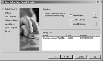
AutoCAD presents three options:
-
Select Objects allows you to extract data from selected blocks only.
-
The Current Drawing option tells AutoCAD to extract data from all the blocks in the current drawing.
-
With the Select Drawings option, you can extract data from multiple drawings at one time. (Use the Select files button next to the option to select the drawing files you wish to access.)
We'll use the Current Drawing option. Select it and pick the Next > button.
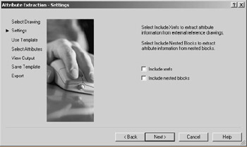
2. On our next dialog box, AutoCAD allows us to include attribute data found in referenced drawings (Xrefs) or nested blocks (blocks within blocks).
-
Our drawing doesn't use Xrefs, so clear that box. (We'll see more about Xrefs in Lesson 22.)
-
Our drawing has no nested blocks, so we can clear that box as well.
Pick the Next > button to continue.
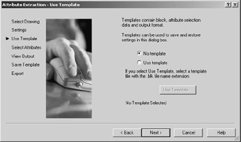
3. The template to which this dialog box refers isn't the same as the template we created in Exercise 19.4.1.1. That template had a .txt extension; the template required here must have a .blk extension. You'll have an opportunity to create a .blk extension later in this exercise. For now, select No template and pick the Next > button to continue.
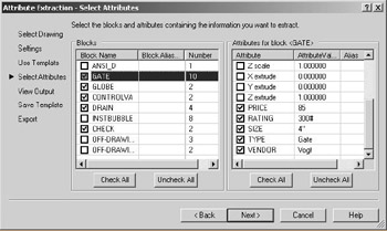
4. Our next dialog box requires some initial work on our part (later we'll be able to select a template and speed past this part).
-
In the left list box, select these blocks: GATE, GLOBE, CONTROLVA, DRAIN, and CHECK. Clear all other blocks.
-
In the right list box, select these attributes for each selected block: PRICE, RATING, SIZE, VENDOR, and TYPE. Clear all other attributes.
Pick the Next > button to continue.
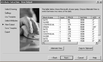
5. AutoCAD politely gives you a preview of your extraction file. (AutoCAD doesn't know exactly how to arrange the attributes in terms of rows and columns. If yours doesn't look like the one shown, pick the Alternate View button.) You can pick the < Back button to make changes or the Next > button to continue. Let's continue.

6. Now AutoCAD gives you the opportunity to save your extraction setup as a template file so that you can use it again later. Pick the Save Template… button.
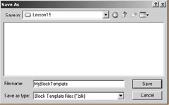
7. Save the template as MyBlockTemplate in the C:\Steps\Lesson19 folder. Pick the Save button to return to the Save Template dialog box; then pick the Next > button to continue.
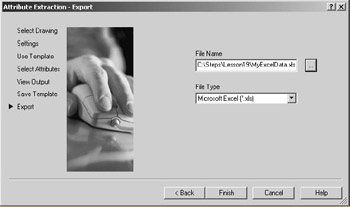
8. In the Attribute Extraction - Export dialog box, you'll select what type of file you want to create. The File Type list box will make file types available that are compatible with applications that are on your computer. I'll select the Microsoft Excel (*.xls) file type. You should select something that is compatible with an application on your own computer.
You should also name and locate your file. (You can pick the button next to the File Name text box to make this easier. I'll save my file as MyExcelData in the C:\Steps\Lesson19 folder.)
Pick the Finish button to complete the procedure.
9. Open the file you created in the application that you selected in Step 8. I'll open mine in MS Excel (Figure 19.4.2.2.9a).
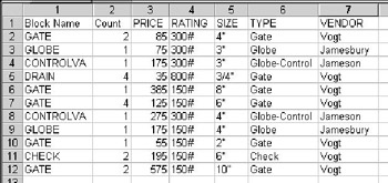
Figure 19.4.2.2.9a -
I give this last procedure a breathless gasp followed by a, "Way cool!"
|
| < Day Day Up > |
|
EAN: 2147483647
Pages: 96