4.9 Exercises
-
Start a new drawing with the following parameters:
1.1
Grid: 1
1.2
Snap: ½
1.3
Lower left limits: 0,0
1.4
Upper right limits: 36,24
1.5
Text Heights: 3/8", 3/16", 1/4" & 1/8"
1.6
Create the organizational chart in Fig. 4.9.1a ( next page). Feel free to substitute names for those used.
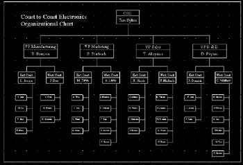
Fig. 4.9.1: Organizational Chart(HINT: Most of my students spend an hour or so drawing a number of rectangles only to discover that the text won't fit, then must redraw them after entering the text. Enter the text first .)
1.7
Save the drawing as: MyOrg in the C:\Steps\Lesson04 folder.
-
Create the Isometric Block drawing in Fig. 4.9.2a, complete with text. Use the MyIsoGrid1 template file you created in the C:\Steps\Lesson03 folder. [If that file isn't available, use the IsoGrid1 file in the same folder.] Don't do the dimensions. Save the drawing as MyIsoTxt in the C:\Steps\Lesson04 folder.
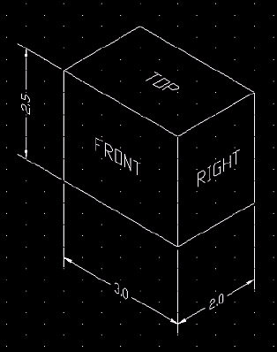
Fig. 4.9.2: Isometric Block -
Create the Border drawing in Fig. 4.9.3b using the following parameters:
3.1
Grid: start with 1
3.2
Snap: as needed
3.3
Lower left limits: 0,0
3.4
Upper right limits: 36,24
3.5
Text size : 3/8, ¼, 1/8
3.6
Border starts at ½, ½ and is ½" in from the limits on all sides (use the Title Block Detail to help)
3.7
Save the drawing as MyBorder in the C:\Steps\Lesson04 folder.
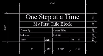
Figure 4.9.3a: Title Block Details
Figure 4.9.3b: Border Drawing -
Using the MyIsoGrid2 template you created in Lesson 3 (or the IsoGrid2 template in the Lesson 3 folder), create the drawing in Fig. 4.9.4a.
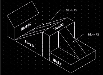
Figure 4.9.4a: Blocks4.1
Text should be ¼" and use the Times New Roman font
4.2
Use the grid to guide your dimensions
4.3
Save the drawing as MyBlocks.dwg in the C:\Steps\Lesson04 folder.
-
Using what you have learned, create the drawings in Figures 4.9.5b through 4.9.5e. Use a 1:1 scale on an 8 ½"x11" sheet of paper for each. I used a ¼" grid when I drew them. Use the title block (fig. 4.9.5a) when creating the border.
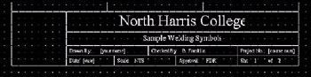
Figure 4.9.5a: Title Block Detail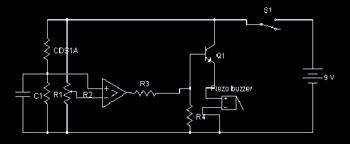
Figure 4.9.5b: Electrical Schematic 4-1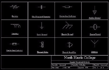
Figure 4.9.5c: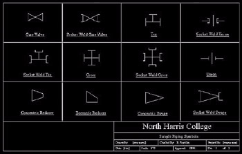
Figure 4.9.5d: Piping Symbols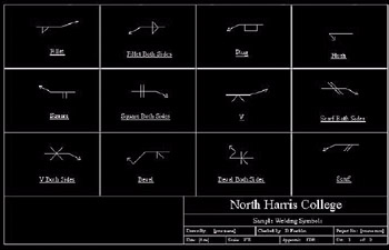
Figure 4.9.5e: Welding Symbols