Flylib.com

Books Software


3.2 And Now the Easy Way - DSettings


3.2 And Now the Easy Way - DSettings

We've seen the command prompt method of setting Grid and Snap . Any setting that requires several lines of entry, as these do, is a prime candidate for a dialog box. AutoCAD has not disappointed.

There are several ways to display the Drafting Settings dialog box. You can enter the command DSettings (or DS ) at the command prompt or rightclick on any of the toggles on the status bar and select Settings from the cursor menu that appears. AutoCAD will present the Drafting Settings dialog box seen in Figure 3.2a.
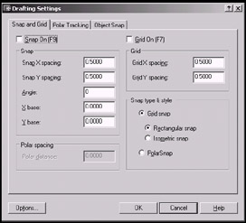
click to expand
Figure 3.2a:

This box has three tabs available to help you (Refer to the figures that follow).

  • Figure 3.2a shows the Snap and Grid tab on top. You'll see this when you select Settings from the cursor menu presented when you right-click on the Snap or Grid toggle on the status bar. This tab presents frames where you can set increments for the Snap spacing (for the grid snap), the Polar spacing (for the polar snap), or the Grid spacing. This tab also provides check boxes for toggling on/off the Snap and Grid , and radio buttons for setting the type of snap ( Polar or Grid , Rectangular or Isometric “ more on isometric snap in Section 3.6, "Isometric Drafting").

  • If you access the Drafting Settings dialog box by right-clicking on the Polar toggle, AutoCAD will place the Polar Tracking tab on top, as seen in Figure 3.2b.
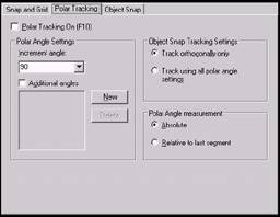
    click to expand
    Figure 3.2b:

    Here you can toggle Polar Tracking on/off using the check box. But more importantly, you can adjust the Incremental Angle Settings (the angles at which Polar Tracking appears) using a drop-down box, or add additional angles (not shown in the drop-down box) by picking the New button. Additional angles will appear in the list box and be used when you place a check in the check box.

    You may also determine whether to use Polar Tracking only orthogonally (at the four quadrants “ 0 °, 90 °, 180 °, and 270 °) or using all the angle settings . The Object Snap Tracking Settings frame provides option boxes for each.

    The Polar Angle measurement frame allows you to show Polar Tracking angles in absolute terms (always showing angles as they relate to AutoCAD's compass points) or relative to the last segment (showing angles as they relate to the last line segment drawn). I recommend using the default Absolute setting to avoid confusion.

  • The Object Snap tab (Figure 3.2c) will appear on top when the Drafting Settings dialog box is accessed by right-clicking on the OSNAP or OTrack toggles. Here you can set Running Object Snaps (OSNAPs). We'll look at OSNAPs and Running OSNAPs in Sections 3.3 and 3.4.
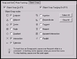
    click to expand
    Figure 3.2c:


3.3 Never Miss the Point with OSNAPs

We've now seen several ways to draw with precision. What more could we possibly need? Well, not all of these tools lend themselves easily to large drawing environments like those found in disciplines such as architecture or petrochemical . This leads us back to a need for some tools that free us as much as possible from the Cartesian Coordinate System. Enter ObjectSnaps “ OSNAPs.

These remarkable tools must and will become second nature to the successful CAD operator. After learning OSNAPs, you must engrain this 11 th Commandment into your hearts and minds: Thou shalt not eyeball! Because after learning OSNAPs, there will never again be a need to guess about the location of a point.

What are OSNAPs? OSNAPs are a means of responding with precision to any prompt directing you to pick a point in your drawing. They provide the means for precisely locating and selecting a point (endpoint, midpoint , center point, etc) on (or referenced by) any existing object in the drawing “ lines, circles, arcs, and so forth.

Study the following chart. The first column shows the buttons found on the OSNAP toolbar. The middle column shows the cheater symbols AutoCAD shows when trying to use an OSNAP in a drawing. The last column shows the equivalent command found when you call up the cursor menu by clicking the right mouse button (with your cursor in the drawing area), while holding down the shift key on the keyboard.

Osnap Toolbar

Symbol

Cursor Menu


Temporary Track Point


From

Endpoint

Midpoint

Intersection

Apparent Intersection

Extension

Center

Quadrant

Tangent

Perpendicular

Parallel

Insert

Node

Nearest


None


Osnap Settings

Most of these will become obvious once you've used them. Some will require a bit more explanation. The best way to learn how to use object snaps , though, is through a practice exercise. Follow me!

Do This: 3.3.1 OSNAP Practice

  1. Open the train.dwg file found in the C:\Steps\Lesson03 folder. It'll look like Figure 3.3.1a (without the numbers and arrows).


    Figure 3.3.1a:

  2. Show the OSNAP toolbar and dock it to the right side of your screen. [Right-click on any visible toolbar and select Object Snap from the cursor menu. When the toolbar appears, pick and hold with the left mouse button in the blue title bar, dragging the toolbar until it docks against the right side of the graphics area.]

  3. Follow these steps. For this exercise, I will use three methods of selecting OSNAPs, but the methods are completely interchangeable.

    Tools

    Command Sequence

    Steps

    click to expand

    1. Check the status bar and be sure that all the toggles shown here are raised. If any of the toggles appear depressed, pick on it once to raise it.

    Command: l

    2. We'll begin at the front of the train. Enter the Line command.

    Endpoint Button

    Specify first point: _endp of

    3. Pick the Endpoint OSNAP button on the OSNAP toolbar.


    4. Place the cursor at point 1 on Figure 3.3.1a. Notice how a small square (the symbol for endpoint shown on the chart on the previous page) appears at the endpoint of the line (as shown). Pick here.

    Notice that the line begins at the endpoint of the existing line.

    Specify next point or [Undo]: _endp of

    5. Select the Endpoint button again.


    Specify next point or [Undo]: [enter]

    6. Place the cursor at Point 2. Notice the symbol for endpoint appears. Pick here. Your line is drawn to the endpoint.

    Hit enter to complete the command.


    7. Next we'll draw a cowcatcher using the Line command, the Extension OSNAP, and Polar Tracking.

    First, let's set up the Polar Tracking. Right- click on the Snap toggle on the status bar, and select Settings from the menu.

    click to expand

    8. AutoCAD presents the Drafting Settings dialog box with the Snap and Grid tab on top, as seen in Figure 3.2a. Place a bullet next to Polar Snap , and then set the Polar distance at .25 as shown. Check the Snap On check box; then pick on the Polar Tracking tab.

    9. We'll want to use Polar Tracking on all angles, so put a bullet in the Track using all polar angle settings option of the Object Snap Tracking Settings frame as shown.

    Check the Polar Tracking On check box; then pick the OK button to complete the setup.

    Command: l

    10. Begin the Line command.

    Extension Button


    11. Pick the Extension OSNAP button.

    12. Place your crosshairs over Point 1, but don't pick . AutoCAD will display a small plus symbol indicating that the object has been located. Move your cursor down and slightly to the left. Notice the cheater box as Polar Tracking helps you locate a point off of the extension of the line that you created in Steps 2 through 6.

    Pick at the point located ¾" at 263 ° as shown.


    13. Now use Polar Tracking to create a rectangle ¼" up and 2" to the left.


    14. Using the Endpoint OSNAP, draw a line connecting the upper right corner of the cowcatcher to Point 1, as shown in Figure 3.3.1.14a.


    click to expand
    Figure 3.3.1.14a:

    Command: l

    Specify first point: _endp of

    15. Use the Endpoint OSNAP to begin a line at the upper left corner of the cowcatcher.


    Specify next point or [Undo]: [enter]

    16. At the Specify next point prompt, type nea to tell AutoCAD you want the point nearest to where you select. (Typing "nea" is the keyboard entry method for using the Nearest OSNAP.) Select a point near Point 3. Notice the symbol.


    Specify next point or [Undo]: nea

    17. Hit enter to complete the command.


    Command: [enter]

    18. Repeat the Line command. This time we'll select a point where two lines would intersect if they were a bit longer. And we'll use the cursor menu to enter the OSNAPs.

    Specify first point: _appint of and

    19. Hold down the shift key on the keyboard and right-click in the graphics area of the screen. You'll see a cursor menu like the one shown here. Select Apparent Intersection .

    AutoCAD asks which nonintersecting lines you wish to use. Select the line you drew between the cowcatcher and Point3; and then select the line at Point 4. Notice the symbols.

    AutoCAD begins the line.

    Specify next point or [Undo]: _par to

    20. Now we must identify where to go with the line.

    Bring up the cursor menu again (as you did in Step 19), and select Parallel . Place your cursor over the line between Points 1 and 2 ( don't pick). AutoCAD will display a plus sign to let you know it has found the line.

    21. Move the cursor to the bottom of the smokestack. Pick when AutoCAD displays the cheater box shown. (Notice that the parallel symbol appears on the line you selected when your line is parallel to it.)


    Specify next point or [Undo]: [enter]

    22. Hit enter to complete the command. Your drawing looks like Figure 3.3.1.22a.


    click to expand
    Figure 3.3.1.22a:


    Command: [enter]

    23. Repeat the Line command.

    Node Button

    Specify first point: nod

    24. Using one of the options we've seen (cursor menu, keyboard, or toolbar button), tell AutoCAD you want to start at a Node . Select the node (the "X") at point 6. (We'll discuss points, or nodes , in Lesson 9.)

    Parallel Button

    Specify next point or [Undo]: _par to

    25. Draw the line to point 7, and parallel to the other smokestack line.


    Specify next point or [Undo]: [enter]

    26. Hit enter to complete the command.


    Command: [enter]

    27. Repeat the Line command.

    Snap From Button

    Specify first point: from

    28. We want the bell assembly to start a bit above the top of the bell. There is not a point there to snap, so we'll use the From option.

    Center Point Button

    Base point: cen of <Offset>: @.25<90

    29. We'll start a line ¼" above ( From ) the center of the circle at point 8. We'll need to use polar coordinates.

    Perpendicular Button

    Specify next point or [Undo]: per

    30. Perpendicular to the line at point 9.


    Specify next point or [Undo]: [enter]

    31. Complete the command. Your drawing now looks like Figure 3.3.1.31a.


    click to expand
    Figure 3.3.1.31a:


    Command: [enter]

    32. Repeat the Line command.

    Specify first point: end

    33. From the endpoint at point 10

    Specify next point or [Undo]: par

    34. parallel to the vertical cab line to point 11.


    Specify next point or [Undo]: [enter]

    35. Complete the command.


    Command: [enter]

    36. Repeat the Line command.

    Specify first point: end

    37. From the endpoint at point 12

    Specify next point or [Undo]: par

    38. parallel to the vertical cab line to point 13.


    Specify next point or [Undo]: [enter]

    39. Complete the command.


    Command: [enter]

    40. Repeat the Line command.

    Specify first point: end

    41. From the endpoint at point 12

    Specify next point or [Undo]: cen

    42. to the center of the circle at point 14.


    Specify next point or [Undo]: [enter]

    43. Complete the command. Your drawing looks like Fig. 3.3.1.43a.


    click to expand
    Fig. 3.3.1.43a:


    Command: [enter]

    44. Repeat the Line command.

    Specify first point: nod

    45. From the node at point 15

    Tangent Button

    Specify next point or [Undo]: tan

    46. t angent to the circle at point 16.


    Specify next point or [Undo]: [enter]

    47. Complete the command.


    Command: [enter]

    48. Repeat the Line command.

    Specify first point: nod

    49. From the node at point 17

    Specify next point or [Undo]: tan

    50. t angent to the circle at point 18.


    Specify next point or [Undo]: [enter]

    51. Complete the command.


    Command: [enter]

    52. Now the flagpole . Repeat the Line command.

    Intersection Button

    From point: int

    53. From the intersection at point 20

    Midpoint Button

    To point: mid

    54. to the midpoint of the line at point 21.


    Command: [enter]

    55. Complete the command. Your drawing now looks like Fig. 3.3.1.55a.


    click to expand
    Fig. 3.3.1.55a:


    Command: saveas

    56. Save the drawing to the C:\Steps\Lesson03\ folder as MyTrain.dwg .

You should now be fairly familiar with three ways to call on OSNAPs “ the toolbar, the keyboard, and the cursor menu.