15.2 Try One
Now that you've some understanding of what it takes to create dimension styles and dimension a drawing, let's dimension our floor plan. As you're building experience with the software, I'm going to let you do as much as you can on your own. Refer back to the appropriate portion of the texts as needed.
Do This: 15.2.1 Dimension the Floor Plan
-
Open your MyFlrPln15.dwg file from the C:\Steps\Lesson15 folder. If it'sn't available, open FlrPln15.dwg in the same folder.
-
Zoom all.
-
Follow these steps.
Tools
Command Sequence
Steps

Command: ddim
1. Create a dimension layer called dim . Assign the color Yellow to your new layer and make it current.

Command: la
2. Open the Dimension Style Manager.
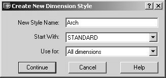
3. Create a new style called Arch . Continue to the New Dimension Style: Arch dialog box.
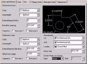
4. Set up the Lines and Arrows tab as shown.
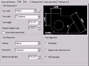
5. Set up the Text tab as shown.
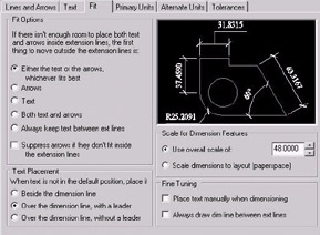
6. Set up the Fit tab as shown.
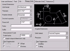
7. Set up the Primary Units tab as shown.

8. We won't need to do any setup on the Alternate Units or Tolerances tabs. Pick the OK button to continue

9. then the Close button to finish the setup.

10. Use the Dimension Style control box on the Dimension toolbar to set the Arch dimstyle current.

Command: qsave
11. Save the drawing but don't exit.
12. Dimension the outer walls as shown in Figure 15.2.1.12a.
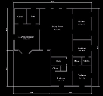
Figure 15.2.1.12a:13. Now dimension the rest of the drawing. Notice that inner walls and door and window openings are dimensioned to their centers. There are a couple ways to do this:
-
use the From OSNAP, or
-
load the Points Lisp routine in the C:\Steps\Lesson10 folder, and use its MW command to place a node midway between two points. Locate the midway point for the doors and windows and use that node for dimensioning.
Your completed drawing looks like Figure 15.2.1.13a.
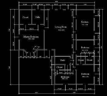
Figure 15.2.1.13a:Command: saveas
14. Save the drawing as MyFlrPln18 to the C:\Steps\Lesson18 folder.
-