8.3 LAN Output
8.3 LAN Output
We're now ready to run traceroute and see the output. We'll use our simple internet (see the figure on the inside front cover) going from svr4 to slip, through the router bsdi. The hardwired SLIP link between bsdi and slip is 9600 bits/sec.
svr4 % traceroute slip traceroute to slip (140.252.13.65), 30 hops max, 40 byte packets 1 bsdi (140.252.13.35) 20 ms 10 ms 10 ms 2 slip (140.252.13.65) 120 ms 120 ms 120 ms
The first unnumbered line of output gives the name and IP address of the destination and indicates that traceroute won't increase the TTL beyond 30. The datagram size of 40 bytes allows for the 20-byte IP header, the 8-byte UDP header, and 12 bytes of user data. (The 12 bytes of user data contain a sequence number that is incremented each time a datagram is sent, a copy of the outgoing TTL, and the time at which the datagram was sent.)
The next two lines in the output begin with the TTL, followed by the name of the host or router, and its IP address. For each TTL value three datagrams are sent. For each returned ICMP message the round-trip time is calculated and printed. If no response is received within 5 seconds for any of the three datagrams, an asterisk is printed instead and the next datagram is sent. In this output the first three datagrams had a TTL of 1 and the ICMP messages were returned in 20, 10, and 10 ms. The next three datagrams were sent with a TTL of 2 and the ICMP messages were returned 120 ms later. Since the TTL of 2 reached the final destination, the program then stopped .
The round-trip times are calculated by the traceroute program on the sending host. They are the total RTTs from the traceroute program to that router. If we're interested in the per-hop time we have to subtract the value printed for TTL N from the value printed for TTL N + 1.
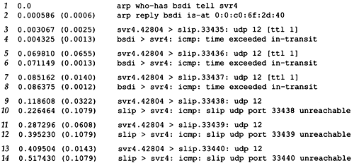
Figure 8.1 shows the tcpdump output for this run. As we might have guessed, the reason that the first probe packet to bsdi had an RTT of 20 ms and the next two had an RTT of 10 ms was because of an ARP exchange. tcpdump shows this is indeed the case.
Figure 8.1. tcpdump output for traceroute example from svr4 to slip.

The destination UDP port starts at 33435 and is incremented by one each time a datagram is sent. This starting port number can be changed with a command-line option. The UDP datagram contains 12 bytes of user data, which we calculated earlier when traceroute output that it was sending 40-byte datagrams.
Next, tcpdump prints the comment [ttl 1] when the IP datagram has a TTL of 1. It prints a message like this when the TTL is 0 or 1, to warn us that something looks funny in the datagram. Here we expect to see the TTL of 1, but with some other application it could be a warning that the datagram might not get to its final destination. We should never see a datagram passing by with a TTL of 0, unless the router that put it on the wire is broken.
The ICMP message "time exceeded in transit" is what we expect to see from the router bsdi, since it will decrement the TTL to 0. The ICMP message comes from the router even though the IP datagram that was thrown away was going to slip.
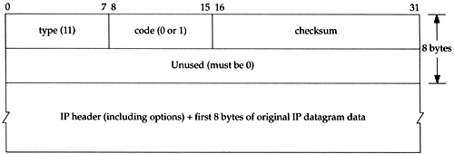
There are two different ICMP "time exceeded" messages (Figure 6.3,), each with a different code field in the ICMP message. Figure 8.2 shows the format of this ICMP error message.
Figure 8.2. ICMP time exceeded message.

The one we've been describing is generated when the TTL reaches 0, and is specified by a code of 0.
It's also possible for a host to send an ICMP "time exceeded during reassembly" when it times out during the reassembly of a fragmented datagram. (We talk about fragmentation and reassembly in Section 11.5.) This error is specified by a code of 1.
Lines 9-14 in Figure 8.1 correspond to the three datagrams sent with a TTL of 2. These reach the final destination and generate an ICMP port unreachable message.
It is worthwhile to calculate what the round-trip times should be for the SLIP link, similar to what we did in Section 7.2 when we set the link to 1200 bits/sec for the Ping example. The outgoing UDP datagram contains 12 bytes of data, 8 bytes of UDP header, 20 bytes of IP header, and 2 bytes (at least) of SLIP framing (Section 2.4) for a total of 42 bytes. Unlike Ping, however, the size of the return datagrams changes. Recall from Figure 6.9 that the returned ICMP message contains the IP header of the datagram that caused the error and the first 8 bytes of data that followed that IP header (which is a UDP header in the case of traceroute ). This gives us a total of 20 + 8 + 20 + 8 + 2, or 58 bytes. With a data rate of 960 bytes/sec the expected RTT is (42 + 58)/960 or 104 ms. This corresponds to the 110-ms value measured on svr4.
The source port number in Figure 8.1 (42804) seems high. traceroute sets the source port number of the UDP datagrams that it sends to the logical-OR of its Unix process ID with 32768. In case traceroute is being run multiple times on the same host, each process looks at the source port number in the UDP header that's returned by ICMP, and only handles those messages that are replies to probes that it sent.
There are several points to note with traceroute. First, there is no guarantee that the route today will be in use tomorrow, or even that two consecutive IP datagrams follow the same route. If a route changes while the program is running you'll see it occur because traceroute prints the new IP address for the given TTL if it changes.
Second, there is no guarantee that the path taken by the returned ICMP message retraces the path of the UDP datagram sent by traceroute. This implies that the round-trip times printed may not be a true indication of the outgoing and returning datagram times. (If it takes 1 second for the UDP datagram to travel from the source to a router, but 3 seconds for the ICMP message to travel a different path back to the source, the printed round-trip time is 4 seconds.)
Third, the source IP address in the returned ICMP message is the IP address of the interface on the router on which the UDP datagram arrived. This differs from the IP record route option (Section 7.3), where the IP address recorded was the outgoing interface's address. Since every router by definition has two or more interfaces, running traceroute from host A to host B can generate different output than from host B to host A. Indeed, if we run traceroute from host slip to svr4 the output becomes:
slip % traceroute svr4 traceroute to svr4 (140.252.13.34), 30 hops max, 40 byte packets 1 bsdi (140.252.13.66) 110 ms 110 ms 110 ms 2 svr4 (140.252.13.34) 110 ms 120 ms 110 ms
This time the IP address printed for host bsdi is 140.252.13.66, the SLIP interface, while previously it was 140.252.13.35, the Ethernet interface. Since traceroute also tries to print the name associated with an IP address, the names can change. (In our example both interfaces on bsdi have the same name.)
Consider Figure 8.3. It shows two local area networks with a router connected to each LAN. The two routers are connected with a point-to-point link. If we run traceroute from a host on the left LAN to a host on the right LAN, the IP addresses found for the routers will be if1 and if3. But going the other way will print the IP addresses if4 and if2. The two interfaces if2 and if3 share the same network ID, while the other two interfaces have different network IDs.
Figure 8.3. Identification of interfaces printed by traceroute.

Finally, across wide area networks the traceroute output is much easier to comprehend if the IP addresses are printed as readable domain names, instead of as IP addresses. But since the only piece of information traceroute has when it receives the ICMP message is an IP address, it does a "reverse name lookup" to find the name, given the IP address. This requires the administrator responsible for that router or host to configure their reverse name lookup function correctly (which isn't always the case). We describe how an IP address is converted to a name using the DNS in Section 14.5.
EAN: 2147483647
Pages: 378