5.3 RARP Examples
5.3 RARP Examples
In our internet we can force the host sun to bootstrap from the network, instead of its local disk. If we run an RARP server and tcpdump on the host bsdi we get the output shown in Figure 5.1. We use the -e flag to have tcpdump print the hardware addresses:
Figure 5.1. RARP request and reply.

The RARP request is broadcast (line 1) and the RARP reply on line 2 is unicast. The output on line 2, at sun, means the RARP reply contains the IP address for the host sun (140.252.13.33).
On line 3 we see that once sun receives its IP address, it issues a TFTP read-request (RRQ) for the file 8CFCOD21.SUN4C. (TFTP is the Trivial File Transfer Protocol. We describe it in more detail in Chapter 15.) The eight hexadecimal digits in the filename are the hex representation of the IP address 140.252.13.33 for the host sun. This is the IP address that was returned in the RARP reply. The remainder of the filename, SUN4C, indicates the type of system being bootstrapped.
tcpdump says that line 3 is an IP datagram of length 65, and not a UDP datagram (which it really is), because we are running tcpdump with the -e flag, to see the hardware-level addresses. Another point to notice in Figure 5.1 is that the length of the Ethernet frame on line 2 appears to be shorter than the minimum (which we said was 60 bytes in Section 4.5.) The reason is that we are running tcpdump on the system that is sending this Ethernet frame ( bsdi ). The application, rarpd, writes 42 bytes to the BSD Packet Filter device (14 bytes for the Ethernet header and 28 bytes for the RARP reply) and this is what tcpdump receives a copy of. But the Ethernet device driver pads this short frame to the minimum size for transmission (60). Had we been running tcpdump on another system, the length would have been 60.
We can see in this example that when this diskless system receives its IP address in an RARP reply, it issues a TFTP request to read a bootstrap image. At this point we won't go into additional detail about how diskless systems bootstrap themselves . (Chapter 16 describes the bootstrap sequence of a diskless X terminal using RARP, BOOTP, and TFTP.)
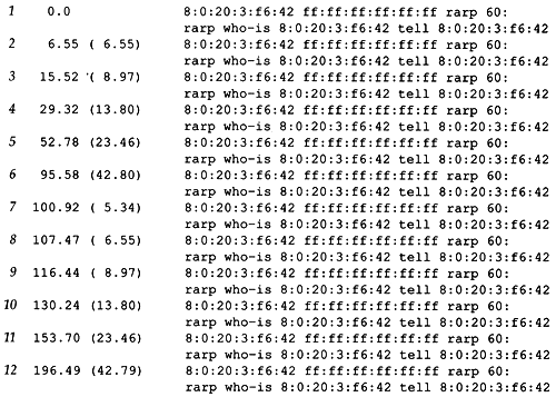
Figure 5.2 shows the resulting packets if there is no RARP server on the network. The destination address of each packet is the Ethernet broadcast address. The Ethernet address following who-is is the target hardware address, and the Ethernet address following tell is the sender's hardware address.
Figure 5.2. RARP requests with no RARP server on the network.

Note the frequency of the retransmissions. The first retransmission occurs after 6.55 seconds and then increases to 42.80 seconds, then goes down to 5.34 seconds, then 6.55, and then works its way back to 42.79 seconds. This continues indefinitely. If we calculate the differences between each timeout interval we see a doubling effect: from 5.34 to 6.55 is 1.21 seconds, from 6.55 to 8.97 is 2.42 seconds, from 8.97 to 13.80 is 4.83 seconds, and so on. When the timeout interval reaches some limit (greater than 42.80 seconds) it's reset to 5.34 seconds.
Increasing the timeout value like this is a better approach than using the same value each time. In Figure 6.8 we'll see one wrong way to perform timeout and retransmission, and in Chapter 21 we'll see TCP's method.
EAN: 2147483647
Pages: 378