Graphics
Whenever you draw in Visual Basic .NET, you need a Graphics object. A Graphics object represents a drawing surface, whether it is a Form, PictureBox, Bitmap in memory, metafile, or printer surface.
The Graphics class provides many methods for drawing shapes and filling areas. It also includes properties and methods that modify the graphics results. For example, its transformation methods enable you to scale, translate, and rotate the drawing output.
The following sections describe the Graphics object’s properties and methods for drawing, filling, and otherwise modifying the drawing.
Drawing Methods
The Graphics object provides many methods for drawing lines, rectangles, curves, and other shapes. The following table describes these methods.
| Method | Description |
|---|---|
| DrawArc | Draws an arc of an ellipse. |
| DrawBezier | Draws a Bézier curve. See the section “DrawBezier” later in this chapter for an example. |
| DrawBeziers | Draws a series of Bézier curves. See the section “DrawBezier” later in this chapter for an example. |
| DrawClosedCurve | Draws a closed curve that joins a series of points, connecting the final point to the first point. See the section “DrawClosedCurve” later in this chapter for an example. |
| DrawCurve | Draws a smooth curve that joins a series of points. This is similar to a DrawClosedCurve, except that it doesn’t connect the final point to the first point. |
| DrawEllipse | Draws an ellipse. To draw a circle, draw an ellipse with a width equal to its height. |
| DrawIcon | Draws an Icon onto the Graphics object’s drawing surface. |
| DrawIconUnstretched | Draws an Icon object onto the Graphics object’s drawing surface without scaling. If you know that you will not resize the icon, this may be faster than the DrawIcon method. |
| DrawImage | Draws an Image object onto the Graphics object’s drawing surface. Note that Bitmap is a subclass of Image, so you can use this method to draw a Bitmap on the surface. |
| DrawImageUnscaled | Draws an Image object onto the drawing surface without scaling. If you know that you will not resize the image, this may be faster than the DrawImage method. |
| DrawLine | Draws a line. |
| DrawLines | Draws a series of connected lines. If you need to draw a series of connected lines, this is much faster than using DrawLine repeatedly. |
| DrawPath | Draws a GraphicsPath object. See the section “DrawPath” later in this chapter for an example. |
| DrawPie | Draws a pie slice taken from an ellipse. |
| DrawPolygon | Draws a polygon. This is similar to DrawLines, except that it connects the last point to the first point. |
| DrawRectangle | Draws a rectangle. |
| DrawRectangles | Draws a series of rectangles. If you need to draw a series of rectangles, this is much faster than using DrawRectangle repeatedly. |
| DrawString | Draws text on the drawing surface. |
The following sections provide examples of some of the more complicated of these drawing methods.
DrawBezier
The DrawBezier method draws a Bézier curve. A Bézier curve is a smooth curve defined by four control points. The curve starts at the first point and ends at the last point. The line between the first and second points gives the curve’s initial direction. The line connecting the third and fourth points gives its final direction as it enters the final point.
The following code draws a Bézier curve. It starts by defining the curve’s control points. It then draws dashed lines connecting the points, so you can see where the control points are in the final drawing. You would omit this step if you just wanted to draw the curve. Next the program sets the Graphics object’s SmoothingMode property to HighQuality, so the program draws a smooth, anti-aliased curve. The SmoothingMode property is described in the section “SmoothingMode” later in this chapter. The program creates a black pen three pixels wide and draws the Bézier curve.
Private Sub Form1_Paint(ByVal sender As Object, _ ByVal e As System.Windows.Forms.PaintEventArgs) Handles MyBase.Paint ' Define the Bezier curve's control points. Dim pts() As Point = { _ New Point(10, 10), _ New Point(200, 10), _ New Point(50, 200), _ New Point(200, 150) _ } ' Connect the points with dashed lines. Using dashed_pen As New Pen(Color.Black, 0) dashed_pen.DashStyle = Drawing2D.DashStyle.Dash For i As Integer = 0 To 2 e.Graphics.DrawLine(dashed_pen, pts(i), pts(i + 1)) Next i End Using ' Draw the Bezier curve. e.Graphics.SmoothingMode = Drawing2D.SmoothingMode.HighQuality Using bez_pen As New Pen(Color.Black, 3) e.Graphics.DrawBezier(bez_pen, pts(0), pts(1), pts(2), pts(3)) End Using End Sub Figure 20-7 shows the result. You can see in the picture how the control points determine the curve’s end points and the direction it takes at them.
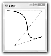
Figure 20-7: The DrawBezier method draws a smooth curve defined by four control points.
DrawBeziers
The DrawBeziers method draws a series of Bézier curves with common end points. It takes as parameters an array of points that determine the curves’ end points and interior control points. The first four entries in the array represent the first curve’s starting point, its two interior control points, and the curve’s end point. The next curve uses the first curve’s end point as its starting point, provides two interior control points, and its own end point. This pattern repeats for each of the curves. To draw N curves, the array should contain 3 * N + 1 points.
The following code draws two Bézier curves. It defines seven points (3 * 2 + 1 = 7) and connects them with dashed lines. It sets the Graphics object’s SmoothingMode property and calls the DrawBeziers method.
Private Sub Form1_Paint(ByVal sender As Object, _ ByVal e As System.Windows.Forms.PaintEventArgs) Handles MyBase.Paint ' Define the Bezier curve's control points. Dim pts() As Point = { _ New Point(10, 10), _ New Point(200, 10), _ New Point(50, 200), _ New Point(200, 150), _ New Point(250, 50), _ New Point(250, 200), _ New Point(100, 250) _ } ' Connect the points with dashed lines. Using dashed_pen As New Pen(Color.Black, 0) dashed_pen.DashStyle = Drawing2D.DashStyle.Dash For i As Integer = 0 To pts.Length - 2 e.Graphics.DrawLine(dashed_pen, pts(i), pts(i + 1)) Next i End Using ' Draw the Bezier curve. e.Graphics.SmoothingMode = Drawing2D.SmoothingMode.HighQuality Using bez_pen As New Pen(Color.Black, 3) e.Graphics.DrawBeziers(bez_pen, pts) End Using End Sub Figure 20-8 shows the result. Notice that the two Bézier curves share a common end point, but they do not meet smoothly. To make them meet smoothly, you would need to ensure that the last two points in the first curve and the first two points in the second curve (one of which is the same as the last point in the first curve) all lie along the same line.
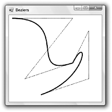
Figure 20-8: The DrawBeziers method draws a series of Bézier curves with common end points.
DrawClosedCurve
Using the DrawBeziers method, you can draw a series of connected curves, but joining them smoothly is difficult. The DrawClosedCurve method connects a series of points with a smooth curve.
The following code draws a closed curve. It defines a series of points, sets the Graphics object’s SmoothingMode property, and calls DrawClosedCurve to draw the curve. It then loops through the curve’s control points, drawing a box over each so you can see where they are.
Private Sub Form1_Paint(ByVal sender As Object, _ ByVal e As System.Windows.Forms.PaintEventArgs) Handles MyBase.Paint ' Define the curve's control points. Dim pts() As Point = { _ New Point(50, 80), _ New Point(200, 50), _ New Point(20, 200), _ New Point(200, 150), _ New Point(250, 50), _ New Point(250, 200), _ New Point(100, 250) _ } ' Draw the closed curve. e.Graphics.SmoothingMode = Drawing2D.SmoothingMode.HighQuality Using curve_pen As New Pen(Color.Black, 3) e.Graphics.DrawClosedCurve(curve_pen, pts) End Using ' Draw rectangles on the control points. For i As Integer = 0 To pts.Length - 1 e.Graphics.FillRectangle(Brushes.White, pts(i).X - 2, pts(i).Y - 2, 5, 5) e.Graphics.DrawRectangle(Pens.Black, pts(i).X - 2, pts(i).Y - 2, 5, 5) Next i End Sub Figure 20-9 shows the result. Notice that the curve is smooth and that it passes through each of the control points exactly. If you just want to connect a series of points smoothly, it is easier to use a closed curve than Bézier curves.
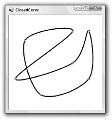
Figure 20-9: The DrawClosedCurve method draws a smooth curve connecting a series points.
The DrawCurve method is similar to DrawClosedCurve, except that it doesn’t connect the last point to the first.
Overloaded versions of the DrawClosedCurve method take a tension parameter that indicates how tightly the curve bends. Usually this value is between 0 and 1. The value 0 makes the method connect the curve’s points with straight lines. The value 1 draws a nicely rounded curve. Tension values greater than 1 produce some strange (but sometimes interesting) results.
The following code draws closed curves with tension set to 0.0, 0.25, 0.5, 0.75, and 1.0. It uses progressively thicker lines so you can see which curves are which.
For tension As Single = 0 To 1 Step 0.25 Using curve_pen As New Pen(Color.Black, tension * 4 + 1) e.Graphics.DrawClosedCurve(curve_pen, pts, tension, _ Drawing2D.FillMode.Alternate) End Using Next tension Figure 20-10 shows the result. You can see the curves growing smoother as the tension parameter increases and the pen thickens.
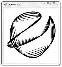
Figure 20-10: The DrawClosedCurve method’s tension parameter determines how tightly the curve bends.
Overloaded versions of the DrawCurve method also take tension parameters.
DrawPath
The DrawPath method draws a GraphicsPath object as shown in the following code. The program creates a new, empty GraphicsPath object and uses its AddString method to add a string to the path. This method takes as parameters a string, FontFamily, font style, font size, point where the text should start, and a string format. The code sets the Graphics object’s SmoothingMode property to draw anti-aliased curves. It then calls the FillPath method to fill the area defined by the GraphicsPath object with white and uses the DrawPath method to draw the path’s outline in black.
Private Sub Form1_Paint(ByVal sender As Object, _ ByVal e As System.Windows.Forms.PaintEventArgs) Handles MyBase.Paint ' Create a GraphicsPath. Using graphics_path As New Drawing2D.GraphicsPath ' Add some text to the path. graphics_path.AddString("GraphicsPath", _ New FontFamily("Times New Roman"), _ CInt(FontStyle.Bold), _ 80, New Point(10, 10), _ StringFormat.GenericTypographic) ' Draw the path. e.Graphics.SmoothingMode = SmoothingMode.AntiAlias e.Graphics.FillPath(Brushes.White, graphics_path) Using thick_pen As New Pen(Color.Black, 3) e.Graphics.DrawPath(thick_pen, graphics_path) End Using End Using End Sub Figure 20-11 shows the result.
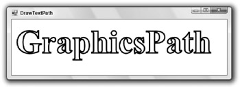
Figure 20-11: The DrawPath method draws the outline defined by a GraphicsPath object.
You can use GraphicsPath objects to make all sorts of interesting effects. For example, you could fill a GraphicsPath with a color gradient, hatch pattern, or bitmap.
Filling Methods
The Graphics object provides many methods for filling areas. These correspond exactly to the drawing methods that define a closed shape. For example, DrawRectangle draws a rectangle and FillRectangle fills one.
Corresponding draw and fill methods take exactly the same parameters, except that the drawing methods use a Pen object whereas the filling methods use a Brush object. For example, the following statements fill and draw a GraphicsPath object. The only difference in the parameters is the Pen or Brush.
e.Graphics.FillPath(Brushes.White, graphics_path) e.Graphics.DrawPath(Pens.Black, graphics_path) The Graphics object provides the following methods for filling areas: FillClosedCurve, FillEllipse, FillPath, FillPie, FillPolygon, FillRectangle, and FillRectangles. These methods work the same way as the corresponding drawing methods (DrawClosedCurve, DrawEllipse, DrawPath, DrawPie, DrawPolygon, DrawRectangle, and DrawRectangles), except they fill an area with a brush rather than drawing it with a pen. See the section “Drawing Methods” earlier in this chapter for descriptions of these methods.
Other Graphics Properties and Methods
The following table describes the Graphics object’s most useful properties and methods, other than those that draw or fill shapes.
| Properties/Methods | Description |
|---|---|
| AddMetafileComment | If the Graphics object is attached to a metafile, this adds a comment to it. Later, if an application enumerates the metafile’s records, it can view the comments. |
| Clear | Clears the Graphics object and fills it with a specific color. For example, a form’s Paint event handler might use the statement e.Graphics.Clear(Me.BackColor) to clear the form using its background color. |
| Clip | Determines the Region object used to clip a drawing on the Graphics surface. Any drawing command that falls outside of this Region is clipped off and not shown in the output. |
| Dispose | Releases the resources held by the Graphics object. You can use this method to free the resources of an object that you no longer need sooner than they would be freed by garbage collection. For a more detailed discussion, see the section “Dispose” in Chapter 16. |
| DpiX | Returns the horizontal number of dots per inch (DPI) for this Graphics object’s surface. |
| DpiY | Returns the vertical number of DPI for this Graphics object’s surface. |
| EnumerateMetafile | If the Graphics object is attached to a metafile, this sends the metafile’s records to a specified callback subroutine one at a time. |
| ExcludeClip | Updates the Graphics object’s clipping region to exclude the area defined by a Region or Rectangle. |
| FromHdc | Creates a new Graphics object from a handle to a device context (DC). (A device context is a structure that defines an object’s graphic attributes: pen, color, fill, and so forth. Usually, you can use the GDI+ drawing routines and ignore DCs. They are more useful if you need to use older GDI functions.) |
| FromHwnd | Creates a new Graphics object from a window handle (hWnd). |
| FromImage | Creates a new Graphics object from an Image object. This is a very common way to make a new Graphics object to manipulate a bitmap. |
| InterpolationMode | Determines whether drawing routines use anti-aliasing when drawing images. See the section “InterpolationMode” later in this chapter for an example. |
| IntersectClip | Updates the Graphics object’s clipping region to be the intersection of the current clipping region and the area defined by a Region or Rectangle. (The clipping region determines where GDI+ will draw output. If a line falls outside of the clipping region, GDI+ doesn’t draw the part that sticks out. Normally, an image’s clipping region includes its whole visible area, but you can redefine it so that, for example, parts of the visible area are not drawn.) |
| IsVisible | Returns True if a specified point is within the Graphics object’s visible clipping region. |
| MeasureCharacterRanges | Returns an array of Region objects that show where each character in a string will be drawn. |
| MeasureString | Returns a SizeF structure that gives the size of a string drawn on the Graphics object with a particular font. |
| MultiplyTransform | Multiplies the Graphics object’s current transformation matrix by another transformation matrix. |
| PageScale | Determines the amount by which drawing commands are scaled. For example, if you set this to 2, then every coordinate and measurement is scaled by a factor of 2 from the origin. |
| PageUnits | Determines the units of measurement. This can be Display (1/75 inch), Document (1/300 inch), Inch, Millimeter, Pixel, or Point (1/72 inch). |
| RenderingOrigin | Determines the point used as a reference when hatching. Normally this is (0, 0), so all HatchBrushes use the same RenderingOrigin and, if you draw two overlapping hatched areas, their hatch patterns line up. If you change this property, you can make their hatch patterns not line up. |
| ResetClip | Resets the object’s clipping region, so the drawing is not clipped. |
| ResetTransformation | Resets the object’s transformation matrix to the identity matrix, so the drawing is not transformed. |
| Restore | Restores the Graphics object to a state saved by the Save method. See the section “Saving and Restoring Graphics State” later in this chapter for an example. |
| RotateTransform | Adds a rotation to the object’s current transformation. This rotates all drawing by a specified amount. See the section “Transformation Basics” later in this chapter for an example. |
| Save | Saves the object’s current state in a GraphicsState object, so you can later restore it by calling the Restore method. See the section “Saving and Restoring Graphics State” later in this chapter for an example. |
| ScaleTransform | Adds a scaling transformation to the Graphics object’s current transformation. This scales all drawing by a specified factor in the X and Y directions. See the section “Transformation Basics” later in this chapter for an example. |
| SetClip | Sets or merges the Graphics object’s clipping area to another Graphics object, a GraphicsPath object, or a Rectangle. Only parts of drawing commands that lie within the clipping region are displayed. |
| SmoothingMode | Determines whether drawing routines use anti-aliasing when drawing lines and curves. See the section “SmoothingMode” later in this chapter for an example. |
| TextRenderingHint | Determines whether text is drawn with anti-aliasing and hinting. See the section “TextRenderingHint” later in this chapter and the section “System.Drawing.Text” earlier in this chapter for more details. |
| Transform | Gets or sets the Graphics object’s transformation matrix. This matrix represents all scaling, translation, and rotation applied to the object. |
| TransformPoints | Applies the object’s current transformation to an array of points. |
| TranslateTransform | Adds a translation transformation to the Graphics object’s current transformation. This offsets all drawing a specified distance in the X and Y directions. See the section “Transformation Basics” later in this chapter for an example. |
The following sections give examples of some of the more important (but confusing) Graphics properties and methods.
Anti-Aliasing
Aliasing is an effect caused when you draw lines, curves, and text that do not line up exactly with the screen’s pixels. For example, if you draw a vertical line, it neatly fills in a column of pixels. If you draw a line at a 45-degree angle, it also fills a series of pixels that are nicely lined up, but the pixels are a bit farther apart and that makes the line appear lighter on the screen. If you draw a line at some other angle (for example, 30 degrees), then the line does not line up exactly with the pixels. The line will contain some runs of two or three pixels in a horizontal group. The result is a line that is lighter than the vertical line and that is noticeably jagged.
A similar affect occurs when you resize an image. If you enlarge an image by simply drawing each pixel as a larger block of the same color, the result is blocky. If you shrink an image by removing some pixels, the result may have tears and gaps.
Anti-aliasing is a process that smoothes out lines, text, and images. Instead of drawing a series of pixels that all have the same color, the drawing routines give pixels different shades of color to make the result smoother.
The Graphics object provides three properties that control anti-aliasing for lines and curves, text, and images: SmoothingMode, TextRenderingHint, and InterpolationMode.
SmoothingMode
The SmoothingMode property controls anti-aliasing for drawn lines and curves, and for filled shapes. This property can take the values AntiAlias, Default, HighQuality, HighSpeed, and None. The following code shows how a program might draw a circle’s outline and a filled circle using the HighQuality SmoothingMode:
gr.SmoothingMode = SmoothingMode.HighQuality gr.DrawEllipse(Pens.Black, 10, 10, 20, 20) gr.FillEllipse(Brushes.Black, 30, 10, 20, 20) Figure 20-12 shows the effects of each of the SmoothingMode properties. It’s not clear whether there’s any difference between the Default, HighSpeed, and None modes, or between HighQuality and AntiAlias, at least on this computer. The HighQuality and AntiAlias modes are noticeably smoother than the others, however.
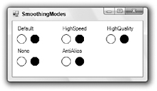
Figure 20-12: The Graphics object’s SmoothingMode property controls anti-aliasing for lines, curves, and filled shapes.
TextRenderingHint
The TextRenderingHint property controls anti-aliasing for text. This property can take the values AntiAlias, AntiAliasGridFit, ClearTypeGridFit, SingleBitPerPixel, SingleBitPerPixelGridFit, and SystemDefault. The following code shows how a program can draw text using the TextRenderingHint value AntiAliasGridFit:
gr.TextRenderingHint = TextRenderingHint.AntiAliasGridFit gr.DrawString("TextRenderingHint", Me.Font, Brushes.Black, 10, 10) Figure 20-13 shows the effects of each of the TextRenderingHint values. The TextRenderingHint value SingleBitPerPixel produces a poor result. SystemDefault and SingleBitPerPixelGridFit give an acceptable result (the default appears to be AntiAliasGridFit on this computer). AntiAlias and AntiAliasGridFit give the best results.
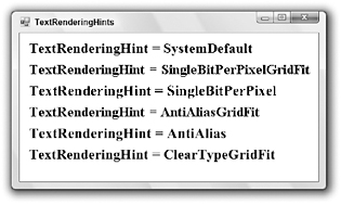
Figure 20-13: The Graphics object’s TextRenderingHint property controls anti-aliasing for text.
Most of the differences are quite subtle. The “grid fit” versions use hinting about where the characters are positioned to try to improve stems and curves. If you look extremely closely (perhaps with a magnifying glass), you can see that the base of the initial T is a bit cleaner and more solid in the AntiAliasGridFit and ClearTypeGridFit modes than in the AntiAlias mode. The “grid fit” modes also provide text that is slightly more compact horizontally than the AntiAlias mode. In any case, each of the last three versions provides a very high-quality result.
InterpolationMode
The InterpolationMode property controls anti-aliasing when a program shrinks or enlarges an image. This property can take the values Bicubic, Bilinear, Default, High, HighQualityBicubic, HighQualityBilinear, Low, and NearestNeighbor.
The following code shows how a program can draw images using the InterpolationMode value HighQualityBilinear. The program starts by creating a Bitmap object and a Graphics object associated with it. It then uses the Graphics object to draw a smiley face on the Bitmap. The program uses the form’s Graphics object’s DrawImage method to draw the Bitmap onto the form at its full size. It then draws the Bitmap at a reduced size and draws the center of the Bitmap enlarged.
Private Sub Form1_Paint(ByVal sender As Object, _ ByVal e As System.Windows.Forms.PaintEventArgs) Handles MyBase.Paint ' Draw a smiley face in the rectangle (0, 0) - (100, 100). Dim bm As New Bitmap(101, 101) Using gr As Graphics = Graphics.FromImage(bm) gr.FillEllipse(Brushes.Yellow, 0, 0, 99, 99) ' Face. gr.DrawEllipse(Pens.Black, 0, 0, 99, 99) gr.DrawArc(Pens.Black, 20, 20, 60, 60, 0, 180) ' Smile. gr.FillEllipse(Brushes.Black, 40, 40, 20, 25) ' Nose gr.FillEllipse(Brushes.White, 25, 15, 20, 25) Left eye. gr.DrawEllipse(Pens.Black, 25, 15, 20, 25) gr.FillEllipse(Brushes.Black, 35, 20, 10, 15) gr.FillEllipse(Brushes.White, 55, 15, 20, 25) ' Right eye. gr.DrawEllipse(Pens.Black, 55, 15, 20, 25) gr.FillEllipse(Brushes.Black, 65, 20, 10, 15) End Using ' Display at full scale at (10, 10)-(110, 110). e.Graphics.DrawImage(bm, 10, 10) ' Display shrunk to fit the rectangle (120, 10)-(170, 60). e.Graphics.InterpolationMode = InterpolationMode.Bilinear e.Graphics.DrawImage(bm, 120, 10, 50, 50) ' Display the Bitmap rectangle (35, 35)-(65, 65) ' enlarged to fit the rectangle (180, 10)-(230, 60). Dim src_rect As New Rectangle(35, 35, 30, 30) Dim dest_rect As New Rectangle(180, 10, 50, 50) e.Graphics.DrawImage(bm, dest_rect, src_rect, GraphicsUnit.Pixel) e.Graphics.DrawRectangle(Pens.Red, dest_rect) End Sub Figure 20-14 shows the effects of each of the InterpolationMode values. The large smiley face in the upper left shows the original image. Each of the other images shows the face shrunk and enlarged. It’s hard to see the differences between the enlarged images (although the NearestNeighbor example is noticeably blockier than the others), but you can easily see breaks in the lower-quality shrunken versions.
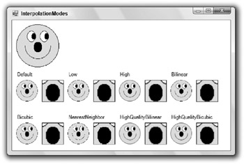
Figure 20-14: The Graphics object’s InterpolationMode property controls anti-aliasing for shrunk or enlarged images.
The InterpolationMode value NearestNeighbor gives the worst result when both shrinking and enlarging. The others give comparable results when enlarging. You can’t see it in the book, but on the screen you can see very small differences between them.
When shrinking the image, however, Default, Low, Bilinear, and Bicubic all show ugly aliasing affects. Pieces of the lines are missing, so the lines appear broken.
The values High, HighQualityBilinear, and HighQualityBicubic produce much smoother results. You probably can’t tell in the book without a microscope, but on the screen HighQualityBilinear gives a slightly better result than HighQualityBicubic and High (which is probably the same as HighQualityBicubic on this computer). These tiny differences will probably depend on the image you are shrinking. For example, most of these effects are much less noticeable when you enlarge and shrink photographs instead of drawn images.
Speed Considerations
The anti-aliasing settings for all three of these properties provide smoother results, but they are slower. For a few lines, strings, and images, the difference in performance won’t be an issue. However, if you build a more intensive application (such as a mapping program that draws several thousand street segments on the form), you may notice a difference in speed.
Transformation Basics
Graphical transformations modify the coordinates and sizes you use to draw graphics to produce a result that is scaled, translated, or rotated. For example, you could apply a scaling transformation that multiples by 2 in the X direction and 3 in the Y direction. If you then drew a line between the points (10, 10) and (20, 20), the result drawn on the screen would connect the points (10 * 2, 10 * 3) = (20, 30) and (20 * 2, 20 * 3) = (40, 60). This stretches the line so it is larger overall, but it stretches its height more than its width (a factor of 3 versus a factor of 2). Notice that this also moves the line farther from the origin [from (10, 10) to (20, 30)]. In general, a scaling transformation moves an object farther from the origin unless it lies on the origin.
You don’t really need to understand all the details of the mathematics of transformations to use them, but a little background is quit helpful.
In two dimensions, you can represent scaling, translation, and rotation with 3 × 3 matrixes. You represent a point with a vector of three entries, two for the X and Y coordinates and a final 1 that gives the vector three entries so that it matches the matrices.
When you multiply a point’s coordinates by a transformation matrix, the result is the transformed point.
To multiply a point by a matrix, you multiply the point’s coordinates by the corresponding entries in the matrix’s columns. The first transformed coordinate is the point’s coordinates times the first column, the second transformed coordinate is the point’s coordinates times the second column, and the third transformed coordinate is the point’s coordinates times the third column.
The following calculation shows the result when you multiple a generic vector <A, B, C> by a matrix. When you work with two-dimensional transformations, the value C is always 1.
| m11 m12 m13 | <A, B, C> * | m21 m22 m23 | | m31 m32 m33 | = <A * m11 + B * m21 + C * m31, A * m12 + B * m22 + C * m32, A * m13 + B * m23 + C * m33> The following matrix represents scaling by a factor of Sx in the X direction and a factor of Sy in the Y direction:
| Sx 0 0 | | 0 Sy 0 | | 0 0 1 | The following example shows the point (10, 20) multiplied by a matrix that represents scaling by a factor of 2 in the X direction and 3 in the Y direction. The result is the vector <20, 60, 1>, which represents the point (20, 60) as you should expect.
| 2 0 0 | <10, 20, 1> * | 0 3 0 | | 0 0 1 | = <10 * 2 + 20 * 0 + 1 * 0, 10 * 0 + 20 * 3 + 1 * 0, 10 * 0 + 20 * 0 + 1 * 1> = <20, 60, 1> The following matrix represents translation through the distance Tx in the X direction and Ty in the Y direction:
| 1 0 0 | | 0 1 0 | | Tx Ty 1 | The following matrix represents rotation through the angle t:
| Cos(t) Sin(t) 0 | | -Sin(t) Cos(t) 0 | | 0 0 1 | Finally, the following transformation, called the identity transformation, leaves the point unchanged. If you multiply a point by this matrix, the result is the same as the original point.
| 1 0 0 | | 0 1 0 | | 0 0 1 | You can work through some examples to verify that these matrices represent translation, scaling, rotation, and the identity, or consult an advanced graphics programming book for proofs.
One of the most useful and remarkable properties of matrix/point multiplication is that it is associative. If p is a point and T1 and T2 are transformation matrices, p * T1 * T2 = (p * T1) * T2 = p * (T1 * T2).
This result means that you can multiply any number of transformation matrices together to create a single combined matrix that represents all of the transformations applied one after the other. You can then apply this single matrix to all the points that you need to draw. This can save a considerable amount of time over multiplying each point by a long series of matrices one at a time.
The Graphics object maintains a current transformation matrix at all times, and it provides several methods that let you add more transformations to that matrix. The ScaleTransform, TranslateTransform, and RotateTransform methods add a new transformation to the current transformation. These methods take parameters that specify the amount by which points should be rotated, scaled, translated, or rotated.
A final parameter indicates whether you want to prepend the new transformation on the left (MatrixOrder .Prepend) or append it on the right (MatrixOrder.Append) of the current transformation. If you prepend the new transformation on the left, that transformation is applied before any that are already part of the current transformation. If you append the new transformation on the right, that transformation is applied after any that are already part of the current transformation.
Strangely, the default if you omit this parameter is to prepend the new transformation on the left. That means the new transformation applies to the point before any other transformations that you have previously applied. That, in turn, means that you must compose a combined transformation backward. If you want to rotate, then scale, then translate, you need to prepend the translation first, the scaling second, and the rotation last. That seems very counterintuitive.
A more natural approach is to explicitly set this final parameter to MatrixOrder.Append so that later transformations are applied after existing ones.
The following code shows how a program can use transformations to draw a complex result with a simple drawing routine. Subroutine DrawArrow draws an arrow within the rectangle 0 <= X <= 4, 0 <= Y <= 4. If you were to call this routine without any transformations, you would see a tiny arrow four pixels long and four pixels wide drawn in the upper-left corner of the form.
This form’s Paint event handler uses the ScaleTransform method to give the Graphics object a transformation that scales by a factor of 30 in both the X and Y directions. It then calls the DrawArrow routine, passing it the parameter HatchStyle.Horizontal. The result is an arrow near the upper-left corner but 30 times larger than the original arrow and filled with a horizontal hatch pattern.
Next the program uses the TranslateTransform method to add a transformation that translates 150 pixels in the X direction and 60 pixels vertically. It appends this transformation so that the drawing is first scaled (the scaling transformation is still part of the Graphics object’s current transformation) and then translated. It calls DrawArrow again, passing it the parameter HatchStyle.Vertical, so the result is an arrow 30 times larger than the original, moved 150 pixels to the right and 60 pixels down, and filled with a vertical hatch pattern.
Finally, the program uses the RotateTransform method to add a transformation that rotates the drawing by 30 degrees clockwise around the origin in the upper-left corner. It again appends the transformation so that the drawing is first scaled, then translated, and then rotated. It calls DrawArrow, passing it the parameter HatchStyle.Cross, so the result is an arrow 30 times larger than the original, moved 150 pixels to the right and 60 pixels down, rotated 30 degrees, and filled with a crosshatch pattern.
' Draw an arrow outline. Private Sub DrawArrow(ByVal gr As Graphics, ByVal hatch_style As HatchStyle) Dim pts() As Point = { _ New Point(0, 1), _ New Point(2, 1), _ New Point(2, 0), _ New Point(4, 2), _ New Point(2, 4), _ New Point(2, 3), _ New Point(0, 3) _ } Using hatch_brush As New HatchBrush(hatch_style, Color.Black, Color.White) gr.FillPolygon(hatch_brush, pts) End Using Using black_pen As New Pen(Color.Black, 0) gr.DrawPolygon(black_pen, pts) End Using End Sub Private Sub Form1_Paint(ByVal sender As Object, _ ByVal e As System.Windows.Forms.PaintEventArgs) Handles MyBase.Paint ' Scale by a factor of 30. e.Graphics.ScaleTransform(30, 30, MatrixOrder.Append) DrawArrow(e.Graphics, HatchStyle.Horizontal) ' Translate 150 horizontally and 60 vertically. e.Graphics.TranslateTransform(150, 60, MatrixOrder.Append) DrawArrow(e.Graphics, HatchStyle.Vertical) ' Rotate 30 degrees. e.Graphics.RotateTransform(30, MatrixOrder.Append) DrawArrow(e.Graphics, HatchStyle.Cross) End Sub Figure 20-15 shows the result.
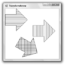
Figure 20-15: This program draws arrows scaled, translated, and rotated.
It is very important to realize that the order in which you apply transformations matters. You cannot change the order of scaling, translation, and rotation and expect the result to be the same.
The following code demonstrates this fact. This version of the DrawArrow subroutine draws a larger arrow that is not positioned in the upper-left corner of the screen. It fills the arrow with white and then outlines it in black. It then draws some text inside the arrow.
The form’s Paint event handler sets the form’s font, enables font anti-aliasing, and uses the DrawArrow subroutine to draw the untransformed arrow. Next, it uses a transformation to translate 150 pixels the X direction and 50 pixels in the Y direction, and draws the arrow again containing the text A1. It then adds a rotation transformation to rotate 45 degrees and draws the arrow again, now containing the text A2.
The program then uses the Graphics object’s ResetTransformation method to remove the translation and rotation. It rotates 45 degrees and draws the arrow containing the text B1. Finally, it translates the same distances as before and draws the arrow one last time, containing the text B2.
' Draw an arrow outline containing some text. Private Sub DrawArrow(ByVal gr As Graphics, ByVal txt As String) ' Draw the arrow. Dim pts() As Point = { _ New Point(80, 20), _ New Point(120, 20), _ New Point(120, 10), _ New Point(140, 30), _ New Point(120, 50), _ New Point(120, 40), _ New Point(80, 40) _ } gr.FillPolygon(Brushes.White, pts) gr.DrawPolygon(Pens.Black, pts) ' Draw the text. Dim layout_rectangle As New RectangleF(80, 20, 50, 20) Dim string_format As New StringFormat string_format.LineAlignment = StringAlignment.Center string_format.Alignment = StringAlignment.Center gr.DrawString(txt, Me.Font, Brushes.Black, _ layout_rectangle, string_format) End Sub Private Sub Form1_Paint(ByVal sender As Object, _ ByVal e As System.Windows.Forms.PaintEventArgs) Handles MyBase.Paint ' Set the font and font anti-aliasing properties. Me.Font = New Font("Times New Roman", 20, FontStyle.Bold, GraphicsUnit.Pixel) e.Graphics.TextRenderingHint = TextRenderingHint.AntiAliasGridFit ' Draw the original arrow. DrawArrow(e.Graphics, "") ' Translate 150 horizontally and 50 vertically. e.Graphics.TranslateTransform(150, 50, MatrixOrder.Append) DrawArrow(e.Graphics, "A1") ' Rotate 45 degrees. e.Graphics.RotateTransform(45, MatrixOrder.Append) DrawArrow(e.Graphics, "A2") ' Reset the transformation. e.Graphics.ResetTransform() ' Rotate 45 degrees. e.Graphics.RotateTransform(45, MatrixOrder.Append) DrawArrow(e.Graphics, "B1") ' Translate 150 horizontally and 50 vertically. e.Graphics.TranslateTransform(150, 50, MatrixOrder.Append) DrawArrow(e.Graphics, "B2") End Sub Figure 20-16 shows the result. The translation followed by rotation gives the arrow labeled A2. The rotation followed by translation gives the arrow labeled B2. It’s clear from the figure that these are not even close to the same results.
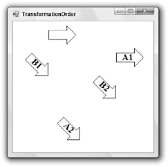
Figure 20-16: A translation followed by a rotation (A1 and A2) is not the same as a rotation followed by a translation (B1 and B2).
The Graphics object’s methods for working with transformations include MultiplyTransform, PageScale, PageUnits, ResetTransformation, RotateTransform, ScaleTransform, Transform, TransformPoints, and TranslateTransform. See the section “Other Graphics Properties and Methods, earlier in this chapter for descriptions of those methods.
Note also that the transformations apply to text as well as drawn lines and filled shapes.
Advanced Transformations
You can build very complex transformations by combining simple ones. For example, you can scale around an arbitrary point by combining simple translation and scaling transformations.
A normal scaling transformation moves an object farther away from the origin. If you scale the point (10, 20) by a factor of 20 in the X and Y directions, you get the point (200, 400), which is much father from the origin. Similarly, if you scale all the points in a shape, all the points move farther from the origin.
To scale the object around some point other than the origin, first translate it so the point of rotation is centered at the origin. Then scale it and translate it back to its original position.
The following code scales a diamond around its center. The DrawDiamond subroutine draws a diamond centered at the point (125, 125). The form’s Paint event handler calls DrawDiamond to draw the original diamond. It then translates to move the diamond’s center to the origin, scales by a factor of 2 vertically and horizontally, and then reverses the first translation to move the origin back to the diamond’s original center.
Private Sub DrawDiamond(ByVal gr As Graphics) Dim pts() As Point = { _ New Point(75, 125), _ New Point(125, 75), _ New Point(175, 125), _ New Point(125, 175) _ } gr.DrawPolygon(Pens.Black, pts) End Sub Private Sub Form1_Paint(ByVal sender As Object, _ ByVal e As System.Windows.Forms.PaintEventArgs) Handles MyBase.Paint ' Draw the original diamond. DrawDiamond(e.Graphics) ' Translate to center at the origin. e.Graphics.TranslateTransform(-125, -125, MatrixOrder.Append) ' Scale by a factor of 2. e.Graphics.ScaleTransform(2, 2, MatrixOrder.Append) ' Translate the center back to where it was. e.Graphics.TranslateTransform(125, 125, MatrixOrder.Append) ' Draw the diamond. DrawDiamond(e.Graphics) End Sub Figure 20-17 shows the result.
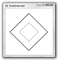
Figure 20-17: To scale an object at a point other than the origin, translate it to the origin, scale it, and then translate it back.
Notice that the lines’ widths have also been scaled by a factor of 2 in this figure. The Pen object’s Width property is a Single, so you can use fractional pen widths if necessary. For example, if you want to scale an object by a factor of 4 and you want the result to have a line width of 2, you can set the Pen’s Width to 0.5 and let it scale.
If you want the final result to have a line width of 1, you can also set the Pen’s Width to 0. This value tells the GDI+ routines to use a single pixel line width, no matter how the drawing is scaled.
Note also that the line width will not go below 1 if you use a scaling transformation to reduce the size of the drawing.
A particularly useful transformation maps a specific rectangle in world coordinates (the coordinates in which you draw) to a specific rectangle in device coordinates (the coordinates on the drawing surface). For example, you might graph a function in the world coordinates -1 <= X <= 1, -1 <= Y <= 1 and want to map it to the drawing surface rectangle 10 <= X <= 200, 10 <= Y <= 200.
To do this, you can first translate to center the world coordinate rectangle at the origin, scale to resize the rectangle to match the size of the device coordinate rectangle, and then translate to move the origin to the center of the device coordinate rectangle.
The MapRectangles subroutine shown in the following code maps a world coordinate rectangle into a device coordinate rectangle for a Graphics object. It begins by resetting the Graphics object’s transformation to clear out anything that may already be in there. Next, the routine translates the center of the world coordinate rectangle to the origin, scales to stretch the world coordinate rectangle to the device coordinate rectangle’s size, and then translates to move the origin to the center of the device-coordinate rectangle.
' Map a world coordinate rectangle to a device coordinate rectangle. Private Sub MapRectangles(ByVal gr As Graphics, _ ByVal world_rect As Rectangle, ByVal device_rect As Rectangle) ' Reset the transformation. gr.ResetTransform() ' Translate to center the world coordinate ' rectangle at the origin. gr.TranslateTransform( _ CSng(-(world_rect.X + world_rect.Width / 2)), _ CSng(-(world_rect.Y + world_rect.Height / 2)), _ MatrixOrder.Append) ' Scale. gr.ScaleTransform( _ CSng(device_rect.Width / world_rect.Width), _ CSng(device_rect.Height / world_rect.Height), _ MatrixOrder.Append) ' Translate to move the origin to the center ' of the device coordinate rectangle. gr.TranslateTransform( _ CSng(device_rect.X + device_rect.Width / 2), _ CSng(device_rect.Y + device_rect.Height / 2), _ MatrixOrder.Append) End Sub The following code shows how a program can use this subroutine to position a drawing. The DrawSmiley subroutine draws a smiley face within the area 0 <= X <= 1, 0 <= Y <= 1. The Paint event handler creates a Rectangle representing the device coordinates where it wants to draw the smiley face. It draws the rectangle so that you can see where the target is. The code then creates a world coordinate rectangle representing the area where the DrawSmiley subroutine draws the face. It calls subroutine MapRectangles to make the necessary transformation and calls DrawSmiley to draw the transformed face.
' Draw a smiley face in the rectangle ' 0 <= X <= 1, 0 <= Y <= 1. Private Sub DrawSmiley(ByVal gr As Graphics) Using the_pen As New Pen(Color.Black, 0) gr.FillEllipse(Brushes.Yellow, 0, 0, 1, 1) ' Face. gr.DrawEllipse(the_pen, 0, 0, 1, 1) gr.DrawArc(the_pen, 0.2, 0.2, 0.6, 0.6, 0, 180) ' Smile gr.FillEllipse(Brushes.Black, 0.4, 0.4, 0.2, 0.25) ' Nose gr.FillEllipse(Brushes.White, 0.25, 0.15, 0.2, 0.25) ' Left eye. gr.DrawEllipse(the_pen, 0.25, 0.15, 0.2, 0.25) gr.FillEllipse(Brushes.Black, 0.35, 0.2, 0.1, 0.15) gr.FillEllipse(Brushes.White, 0.55, 0.15, 0.2, 0.25) ' Right eye. gr.DrawEllipse(the_pen, 0.55, 0.15, 0.2, 0.25) gr.FillEllipse(Brushes.Black, 0.65, 0.2, 0.1, 0.15) End Using End Sub Private Sub Form1_Paint(ByVal sender As Object, _ ByVal e As System.Windows.Forms.PaintEventArgs) Handles MyBase.Paint ' Draw the target rectangle. Dim device_rect As New Rectangle(50, 50, 150, 150) e.Graphics.DrawRectangle(Pens.Black, device_rect) ' Map between world and device coordinate rectangles. Dim world_rect As New Rectangle(0, 0, 1, 1) MapRectangles(e.Graphics, world_rect, device_rect) ' Draw the smiley face. DrawSmiley(e.Graphics) End Sub Figure 20-18 shows the result. Note that the smiley face fits the target device coordinate rectangle nicely.
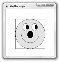
Figure 20-18: This program uses the MapRectangles subroutine to map a smiley face in world coordinates into a rectangle in device coordinates.
The previous example uses subroutine MapRectangles to scale and translate a drawing, but the routine can also stretch or flip the drawing. The program shown in Figure 20-19 is exactly the same as the previous example, except that it uses the following statement to define its device coordinate rectangle:
Dim device_rect As New Rectangle(50, 50, 50, 150) 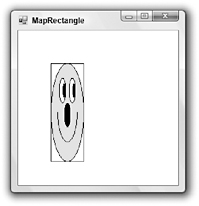
Figure 20-19: The MapRectangles subroutine can stretch a drawing by different amounts vertically and horizontally.
Subroutine MapRectangles can be particularly handy if you need to graph an equation. Normally, in device coordinates, the origin is in the upper-left corner and Y values increase downward. When you draw a graph, however, the origin is in the lower-left corner and Y values increase upward. You could work out how to modify the equation you are trying to draw so that it comes out in the proper orientation, but it’s much easier to use subroutine MapRectangles to flip the Y coordinates.
To invert the Y coordinates, set the device coordinate Rectangle structure’s Y property to the largest Y coordinate you want to use, and set its height to the negative of the height you really want to use. For example, suppose that you want the graph to fill the device coordinate rectangle 50 <= X <= 200, 50 <= Y <= 200. The rectangle has width and height 150, so you would use the following statement to map the coordinate windows:
Dim device_rect As New Rectangle(50, 200, 150, -150) Figure 20-20 shows the same smiley face program used in the previous examples drawn with this mapping. This doesn’t particularly help the smiley face program because the DrawSmiley subroutine was written for a coordinate system where Y increases downward. It is more useful in situations such as graphing, where it is more natural for Y to increase upward.
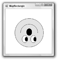
Figure 20-20: The MapRectangles subroutine can flip a drawing’s Y coordinates so that they increase upward instead of downward.
Notice that the target rectangle is not drawn in Figure 20-20 as it was in the previous two versions. The DrawRectangle subroutine won’t draw rectangles with widths or heights less than 1, so the target rectangle doesn’t appear.
You could also use subroutine MapRectangles to flip a drawing’s X coordinates, although the need for that is much less common.
Saving and Restoring Graphics State
The Graphics object’s Save method takes a snapshot of the object’s graphic state and stores it in a GraphicsState object. Later, you can pass this GraphicsState object to the Graphics object’s Restore method to return to the saved state.
Note that you can pass a particular GraphicsState object to the Restore method only once. If you want to use the same state again, you can call the Save method to save it again right after you restore it. That’s the approach used by the following code. The program creates transformations that scale by a factor of 90 and then translate to move the origin to the center of the form. It then starts a loop to draw a rectangle rotated by angles between 5 degrees and 90 degrees.
Within the loop it calls the Save method to record the Graphics object’s current state. That state includes the initial scaling and translation. The loop then adds a rotation transformation to the Graphics object. It passes the RotateTransform method the value MatrixOrder.Prepend, so the rotation is added to the front of the transformation matrix. That makes the combined transformation apply the rotation before the scaling and translation. In other words, drawings are rotated, then scaled, and then translated.
The loop then draws the rectangle -1 <= X <= 1, -1 <= Y <= 1, and then calls Restore to restore the saved graphics state that holds just the scaling and translation.
Private Sub Form1_Paint(ByVal sender As Object, _ ByVal e As System.Windows.Forms.PaintEventArgs) Handles MyBase.Paint Using black_pen As New Pen(Color.Black, 0) ' Scale by a factor of 90. e.Graphics.ScaleTransform(90, 90, MatrixOrder.Append) ' Translate to center on the form. e.Graphics.TranslateTransform( _ Me.ClientRectangle.Width \ 2, _ Me.ClientRectangle.Height \ 2, _ MatrixOrder.Append) For i As Integer = 5 To 90 Step 5 ' Save the state. Dim graphics_state As GraphicsState = e.Graphics.Save() ' Rotate i degrees. e.Graphics.RotateTransform(i, MatrixOrder.Prepend) ' Draw a rectangle. e.Graphics.DrawRectangle(black_pen, -1, -1, 2, 2) ' Restore the saved state. e.Graphics.Restore(graphics_state) Next i End Using End Sub Figure 20-21 shows the result.
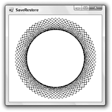
Figure 20-21: This program saves and restores the Graphics object’s state containing a scaling and translation, adding an extra rotation as needed.
There are usually many other ways to achieve the same affect in graphics programming. While changing the order of transformations generally does not give the same result, you can always use different sets of transformations to produce the same outcome.
The following code shows a simpler For loop that creates the same result as the previous version. Rather than using Restore to remove the Graphics object’s current rotation and replacing it with a new one, this version simply adds another 5-degree rotation to the current rotation. For example, a single 10-degree rotation is the same as two 5-degree rotations.
For i As Integer = 5 To 90 Step 5 ' Rotate 5 degrees. e.Graphics.RotateTransform(5, MatrixOrder.Prepend) ' Draw a rectangle. Using black_pen As New Pen(Color.Black, 0) e.Graphics.DrawRectangle(black_pen, -1, -1, 2, 2) End Using Next i Normally, you would not use Save and Restore if such a simple solution is available without them. Save and Restore are more useful when you want to perform several operations using the same transformation and other transformations are interspersed.
The following code shows yet another version. This code creates the initial transformation including the scaling and translation, and then saves the Graphics object’s Transfom property in a transformation matrix variable. Then, in its For loop, the code sets the Graphics object’s Transfom property to this saved matrix before applying the new rotation.
' Save the transformation. Dim trans As Matrix = e.Graphics.Transform For i As Integer = 5 To 90 Step 5 ' Restore the saved transformation. e.Graphics.Transform = trans ' Rotate i degrees. e.Graphics.RotateTransform(i, MatrixOrder.Prepend) ' Draw a rectangle. Using black_pen As New Pen(Color.Black, 0) e.Graphics.DrawRectangle(black_pen, -1, -1, 2, 2) End Using Next i EAN: N/A
Pages: 417