802.11 and Spread Spectrum
| |
A close look at the MAC and Physical layers of wireless LANs.
In a world of cellular telephones and pagers , it's no surprise that the wireless phenomenon has also infiltrated the world of networks. Wireless LANs (WLANs) have found a prominent place in vertical markets such as healthcare, retail, and manufacturing, where workers are often away from a desk, yet they still need to access the wired network.
Although WLANs have practically become staples in these niche areas, a lack of vendor-neutral standards may have hindered those companies that wanted to deploy wireless capabilities for mobile users.
In June 1997, the IEEE 802.11 committee approved a WLAN protocol that defines both the Physical layer (layer 1 on the OSI model) and the MAC layer (the lower part of the Data-Link layer). (See Figure 1 for a graphical representation of the IEEE 802.11 layers.)
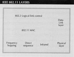
Figure 1: The IEEE 802.11 protocol covers the MAC and Physical (PHY) layer specifications of wireless networking. The standard consists of one MAC that works with three PHYs: two radio frequency and one infrared.
In this tutorial, we will take a closer look at the 802.11 standard and two methods of delivering wireless network capability.
The Big MAC Attack
The Data-Link layer (layer 2) of the OSI model handles a variety of transmission functions, including ensuring that data is packaged properly before it's sent over cabling and performing flow and error control. The upper part of the Data-link layer is called the Logical Link Control sublayer; it ensures that data is reliably sent over the physical link.
The MAC-or Media Access Control-layer, which resides at the lower portion of the Data-link layer, does just as its name states; additionally, it controls access to the physical transmission medium. It's this layer that received a lot of attention from the 802.11 committee.
The 802.11 standard specifies that Carrier Sense Multiple Access with Collision Avoidance , or CSMA/CA, should be used as the method for transmitting information in a WLAN. This may look familiar to anyone with a basic working knowledge of the Ethernet standard; Ethernet uses CSMA/CD (CSMA/Collision Detection) as its transmission protocol.
The CSMA part of both of these methods determines whether the transport medium is currently busy with another transmission. But in cases where two or more end stations hear a quiet network and start to blast information at about the same moment, collision is inevitable. With Ethernet, the CD part of the equation allows packets to be re-sent in the event of collision.
It makes sense for 802.11 to share MAC layer aspects with Ethernet, since in many cases a wireless network will be tied into a wired Ethernet network. But as you can imagine, CD doesn't quite work on a WLAN. For one, CD would require that wireless radios be able to send and receive at the same timea requirement that would increase the price of products and make them more complex. For another reason, on a wireless network it's not always a given that each station can hear all the other stations, as is the case with a wired Ethernet LAN. Because all stations can't necessarily hear each other, a sending station that is free to transmit has no way of knowing if the receiving station is not busy as well.
Instead, 802.11 supports CSMA/CA along with something called positive acknowledge , which differs a bit from CSMA/CD. With the collision avoidance method, a station that wants to transmit first checks the medium to see if it's free. If it is free, then the station is allowed to send. The station on the receiving end of the transmission then dispatches an acknowledgment to inform the sending station that a collision did not occur. If the sending station doesn't receive an acknowledgment packet, it will assume the original packet did not make it through and will resend until an acknowledgment is received.
To minimize the possibility of collision due to stations not being able to hear each other, 802.11 defines a virtual-carrier sense feature. This allows for a station that wants to send something to first send a Request to Send (RTS), which is a short packet that contains the source and destination addresses, as well as the duration of the transmission. If the medium is free, the receiver station will then reply with a short packet called Clear to Send (CTS), which will include the same duration-of-transmission information (see Figure 2).
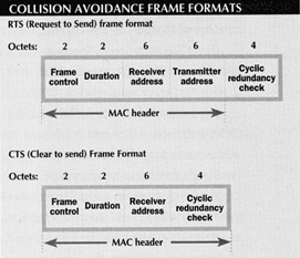
Figure 2: Unlike Ethernet, which includes a Collision Detection (CD) feature, WLANs use Collision Avoidance (CA). Before sending packets, the sending station transmits a Request to Send (RTS); the destination station then sends a Clear to Send (CTS) packet. Only when this occurs will the medium be reserved for the duration of the transmission.
The total duration is the time in microseconds that it takes to send the next information packet, plus a CTS frame, an acknowledgment packet, and three Short Interframe Space (SIFS) intervals. The SIFS separates transmissions in the same dialogue.
Stations that receive the RTS, the CTS, or both packets will set their network allocation vector, which is a virtual carrier sense indicator, to the designated duration, which will then be used when sensing the medium. By sending out these short RTS and CTS packets, the likelihood of collision drops because stations that may not normally be able to hear each other will know to consider the medium busy until the end of the transmission.
This is a brief description of some of the technical details behind a WLAN's layer 2 functions. But as with any traditional wired network, like Ethernet and Token Ring, the Physical layer is necessary to get raw information from one place to another.
Physical Activity
The MAC layer, as we've seen, is crucial to getting information from one place to another safely and reliably. The 802.11 protocol defines one MAC that interacts with three different Physical layers (PHYs). The PHY of the OSI model brings an interface to the network medium and provides the actual signaling function across the network.
802.11 defines two radio frequency PHYs, both of which are variations of spread spectrum, a technology that's been around since World War II. Spread spectrum radio technology was used during the war because it was largely immune to enemy interference and jamming. The transmission signal is, as the name suggests, spread over a wide range of the radio spectrum. These qualities are still desirable for companies that trust the airwaves to transmit what could often be sensitive information.
The IEEE defines two specific types of spread spectrum technologies: direct sequence and frequency hopping . Both methods operate at the 2.4GHz to 2.4835GHz ISM (Industrial, Scientific, and Medical) band an unlicensed range opened by the FCC.
Direct Sequence Spread Spectrum (DSSS) has been defined by the IEEE to operate at either 1Mbit/sec or 2Mbit/sec speeds. DSSS works by spreading a signal over a wide range of the 2.4GHz frequency band. Initially, DSSS enjoyed a very large installed base of products that operated at the 902MHz to 928MHz band. However, this frequency band was not available for DSSS in all parts of the world. In addition, the width of the frequency band was relatively small, and overcrowding soon became a problem. Today, the 2.4GHz range is available for DSSS usage worldwide, and it encompasses more bandwidth than what's available at the 900MHz band.
Frequency Hopping Spread Spectrum (FHSS) is the method adopted by the majority of vendors developing and shipping WLAN products. This subset of spread spectrum operates at a data rate of 1Mbit/sec, with an option to go as high as 2Mbits/sec.
Instead of spreading the signal over a wide band of frequency, FHSS transmits a short burst of data on one frequency, hops to another frequency and transmits for a short period of time on this frequency, then hops to a new frequency. The exact sequence of frequencies used is known as the hop sequence. This sequence must be synchronized between both sending and receiving stations, or they won't be able to communicate. Also, it's possible to have several communications occurring at the same time across the same frequency bandas long as each uses a unique hop sequence. In most cases, many overlapping channels are feasible . Because of this, and because the 2.4GHz band encompasses a lot of space, it's possible for many separate channels to be transmitted at different sequences.
The FCC requires that 75 or more frequencies be used with FHSS, and that a transmission dwell on a particular frequency for no more than 400 milliseconds . In the event of interference on one frequency, that data is retransmitted at the next frequency hop.
The third PHY defined by the IEEE is infrared, but so far most of the products tied to 802.11 fall into the radio frequency category. Probably because the 802.11 discussion dragged out for years and was mostly centered on radio as the wireless medium, many infrared vendors stopped going to 802.11 committee meetings, but the standard still addresses this issue.
What's The Difference
FHSS may appear to be the most popular PHY among both vendors and customers, but both spread spectrum methods of transmission have their place within companies using WLAN technology. Because FHSS signals constantly move around within the 2.4GHz band, anyone trying to listen in will find it just about impossible to pick up any of the signal. Also, the very nature of FHSS lends itself to areas with a heavy density of wireless users.
Technically, DSSS may not be as secure as FHSS, because its signals don't hop around, but anyone listening would only be able to pick up random slices of information. Because the signal is spread out, it becomes very difficult to pick up enough of the signal to do any serious damage. DSSS makes more sense at customer sites such as a warehouse, where users are more spread out and there is little concern for signal interference.
DSSS and FHSS cannot interoperate due to their different methods of transmission. In most cases, companies will settle on one method, or, in some cases, companies may use one method in certain installations and the other at additional sites.
Although companies have been shipping WLAN productssuch as the access points that bridge the wireless with the wired network and the cards that reside within laptops and handheld unitsfor several years, customers haven't had a 100 percent guarantee that products they purchased would conform to the eventual standard. Unless a company purchased all their gear from a single vendor, they couldn't have complete peace of mind that everything would work together.
As with any new standard, the step following approval is interoperability testing among products so customers can be assured that their products will work with those of other vendors.
Resources
For more on the 802.11 protocol, visit the following Web sites:
http://stdsbbs.ieee.org/groups/802/11/index.html
www.breezecom.com/802.11links.html
www.proxim.com/proxim/apps/whiteppr/fh_vs_ds.htm
This tutorial, number 112, by Anita Karv, was originally published in the December 1997 issue of Network Magazine.
| |
EAN: 2147483647
Pages: 193
- Chapter I e-Search: A Conceptual Framework of Online Consumer Behavior
- Chapter VII Objective and Perceived Complexity and Their Impacts on Internet Communication
- Chapter IX Extrinsic Plus Intrinsic Human Factors Influencing the Web Usage
- Chapter XIV Product Catalog and Shopping Cart Effective Design
- Chapter XV Customer Trust in Online Commerce