Fiber and Optical Networking
| |
The foundation of any optical system is the fiber optic cabling, where many challenges of reaching higher transmission speeds are played out. Understanding the types of fibers available, how they work, and their limitations is crucial to mastering next -generation networks.
Basic fiber cables consist of five components . At the center of the cable is the silica core and cladding used for carrying the optic signal. A coating, strength members , and a plastic jacket enclose the fiber, providing the necessary tinsel and scratch resistance to protect the fibers. Attached to both ends of the core are transceivers for emitting and receiving the light pulses that form the information bits in the optical network. The ability of clear glass to contain light is the key behind optical transmissions and is based around the principle of total internal reflection.
Here's how it works: By injecting light at a specific angle, the glass cladding acts as a supermirror, reflecting light within the silica. The trick here has to do with the Refractive Index (RI), or the change in the speed of light in a substance (in this case, silica) relative to the speed of light in a vacuum .
Light normally travels at about 300,000 kilometers (km) per second in a vacuum. However, when light moves from a substance of lower density to one of higher density (say, between air and water), the light changes and is refracted. This is why a stick appears to bend when one half is placed in water.
How much the beam will bend depends on two things: the angle at which light strikes the water and the RI. At some point an angle is reached so that the light reflects off the water like a mirror. This is the critical angle, and the reflection of all the light is the total internal reflection.
This same principle determines how light propagates down a clear fiber. Fibers are manufactured so that the core contains a slightly higher RI than the surrounding cladding. If light travels through the core and hits the cladding at a particular angle, it will stay in the fiber. The exact size of the angle depends on the difference in RIs, but if a typical RI difference of 1 percent is assumed, all light striking the cladding at eight degrees or under will continue on in the fiber (see Figure 1).
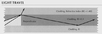
Figure 1: All waves that strike the cladding beyond 82 degrees from the perpendicular propagate down the fiber. Waves that fall within 82 degrees go into the cladding.
Transmission Windows
Of course, the light used in fiber optic transmission isn't the same as the light in a flashlight. The light sources in an optical network are more precise. The ITU has specified six transmission bands for fiber optic transmissions. These bands are expressed in terms of wavelength sizes measured in nanometers (nm), one billionth of a meter, or microns (m), one thousandth of a meter. The six bands are the O-Band (1,260nm to 1,310nm), the E-Band (1,360nm to 1,460nm), the S-Band (1,460nm to 1,530nm), the C-Band (1,530nm to 1,565nm), the L-Band (1,565nm to 1,625nm), and the U-Band (1,625nm to 1,675). A seventh band , not defined by the ITU, but used in private networks, runs around 850nm. To put those measurements into perspective, the human hair is about 100m wide. Typically, the higher the transmission window, the lower the attenuation or signal degradation (see Figure 2), but also the more expensive the electronics.
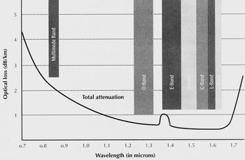
Figure 2: Optical transmission occurs in four windows at varying wavelengths . Except for a small fluctuation around 1.38 microns (1,380 nanometers), the longer the wavelength, the lower the attenuation.
The earliest fibers operated in the first transmission window of 850nm. These standard multimode fibers, or step-index multimode fibers, contained a relatively large core of 50.5m or 62.5m, depending on the cable. They're called multimode because the waves that make up the light take multiple paths or modes through the fiber. How many modes requires some complex calculations, but those numbers easily reach into the hundreds.
These modes cause many problems for step-index fiber, resulting in limited distances. One problem is modal dispersion. Since modes extend through the fiber at different angles, their lengths are slightly different. The result is that light takes less time to travel down some modes (the shorter ones) than others, dispersing or spreading out the light pulse. With short fiber spans there is little spreading out of the pulse, but on longer distances (over a kilometer) the light pulse spreads out so much that it's unreadable.
To increase the range, manufacturers developed Graded Index (GI) fiber, an improved multimode fiber that operates in the second transmission window at around 1,300nm. GI fiber virtually eliminates modal dispersion by gradually decreasing the RI out toward the cladding where the modes are longest. Then waves on the longer modes travel faster than on the shorter modes, so the entire pulse arrives at the receiver at about the same time.
Today, the vast majority of fiber installed in local premises is GI fiber, and with good reason: With GI fiber, manufacturers can extract 200MHz of bandwidth over 2km. "A stepped index fiber would be a tenth of that or worse ," says Eric Anderson, product line manager in the technology development department at Microtest (www.microtest.com), a manufacturer of cable test equipment.
But on distances over 2km, GI fibers need high- powered lasers. This combination introduces the problem of modal noise. With modal noise, the fiber and connectors interact so that there are power fluctuations at the receivers. This often greatly increases the signal-to-noise ratio in a link, limiting the length of the fiber.
Single-Mode Fiber
By using a much narrower core of 8m to 10m, only one mode of light travels over the fiber. Actually, there are two modes, but they are normally independent of one another. With a single mode, many multimode problems, such as modal noise and modal dispersion, are no longer an issue.
Cost, however, is an issue. The minute size of these cores demands that components have much tighter tolerance, which increases costs. These costs, however, are easily outweighed by the increased bandwidth and distances of 80km and longer. There are two main types of single-mode fiber: Non Dispersion Shifted Fiber (NDSF) and Dispersion Shifted Fiber (DSF). DSF comes in two types: Zero Dispersion Shifted Fiber (ZDSF) and Non Zero Dispersion Shifted Fiber (NZDF).
Like GI fibers, the earliest single-mode fiber, NDSF, also carries signals in the second transmission window at 1,310nm. Although NDSF, like all single-mode fiber, greatly improves on GI fiber's range, there are other problems, namely chromatic dispersion. Any light pulse, no matter how precise the laser, contains a range of waves at different frequencies. Since the impact of the RI varies with the wave's frequency, the waves end up propagating down the fiber at different velocities, and the pulse disperses until the signal becomes unintelligible.
At the same time, "waveguide" dispersion also affects wavelength velocity. As waves move down the wire, parts of the electric and magnetic fields extend into the cladding, where the RI is lower. The longer the wavelength, the more energy carried in the claddingand the faster the wave travels. At the second transmission window (around 1,310nm), chromatic dispersion and waveguide dispersion cancel each other. Outside of that window, dispersion increases, limiting the length of the fiber.
Here lies the problem. The third and fourth transmission windows are better suited for longer distances than the second transmission window. They have lower attenuation and can work with the best optical amplifiers, Erbium-Doped Fiber Amplifiers (EDFAs).
Dispersion Shifted Fibers (DSFs) move optimal dispersion points to higher frequencies by altering the core-cladding interface. ZDSF moves the zero dispersion frequency from 1,310nm by increasing the waveguide dispersion until it cancels out chromatic dispersion at 1,550nm. The problem? DWDM gear and EDFAs operate in this window. Signals traveling over ZDSF can combine to create additional signals that may be amplified by EDFAs and superimposed onto Dense Wavelength Division Multiplexing (DWDM) channels, causing noise in a problem known as "four-wave mixing."
NZDF avoids four-wave mixing by moving the zero dispersion point above the range of EDFAs. The signal continues to operate in the third or fourth transmission windows with only a moderate amount of dispersion, which actually helpsas it provides a minimal level of interference needed to separate DWDM channels from one another. Therefore, NZDF is the preferred cable for new optic installations.
Today, manufacturers have reduced the attenuation and the transmission window restriction on NZDF cables. Lucent Technologies' All Wave, for example, works at a frequency range of 1,310nm to 1,550nm without the attenuation peak of around 1,380nm. Similarly, the company optimized its Metrowave cable for 1,310nm and 1,550nm, offering providers an easy migration path to higher spectrums .
Resources
There's a huge amount of material about optical transmissions both in print and on the Web. Two books to check out are Understanding Optical Communications by Harry Dutton and Understanding Fiber Optics by Jeff Hecht. Hecht's book is more readable, but Dutton's covers everything about optical transmissions, with all of the gory engineering details.
Plenty can be found on the Web, as well. A great primer on physics can be found at www. colorado .edu/physics/2000/index.pl?Type=TOC/. A good optical primer can be found at www.vislab.usyd.edu.au/ photonics /fibres/index.html.
This tutorial, number 156, by David Greenfield, was originally published in the July 2001 issue of Network Magazine.
| |
EAN: 2147483647
Pages: 193