Chapter 7: Implementing Secure Wireless Networks
|
|
Introduction to the Wireless LAN
Wireless local area networking (WLAN) is not exactly a new technology, but it has gained rapid acceptance in the past two years and is in wide use now with new deployments being set up every day. In the next sections we look at both the good and the bad of wireless networking. With any technology this young, it should come as no surprise that it has distinct problems—primarily in securing wireless networks. In addition to discussing these problems, we look at an example of the basic architecture and operation of the most typical wireless networking technology you will likely see in your organization: IEEE 802.11b WLAN technology.
Benefits of the Wireless LAN
Wireless networking provides a new era of data connectivity unmatched by cabled networks. Increases in the speed of deployment, access to data, and scalability mean that the needs of specific user communities can be addressed in ways that were unavailable to network architects a few years ago.
New streams of end-user applications and services are being developed to provide businesses and consumers alike with advanced data access and manipulation. The main benefits of wireless integration fall primarily into two major categories:
-
Convenience
-
Productivity
| Test Day Tip | Microsoft gives almost no WLAN security objectives for this exam. In order to better prepare you, this chapter provides a wealth of background information about IEEE 802.11b WLAN information. If you do not want to learn about WLAN technologies and issues, you can skip directly to the "Configuring Windows Client Computers for Wireless LAN Security" section later in this chapter to get the basic information you need for this exam objective. If you are new to WLANs or want to build your knowledge a bit, you should read this entire chapter. |
Convenience
First and foremost in the minds of IT professionals, business leaders, and consumers when they discuss wireless networking is the aspect of convenience. This basic benefit outweighs all other benefits combined in terms of user interest in wireless and is predominantly the main reason for their deployments. Convenience can be broken into three areas of interest:
-
Flexibility
-
Roaming
-
Mobility
Flexibility
Wireless technologies provide the greatest flexibility of design, integration, and deployment of any networking solution available. With only transceivers to install in the local station and a wireless hub or Access Point (AP) to be configured for local access, it is simple to retrofit wireless networking within existing structures or create access services that traditional networking infrastructures are not capable of addressing.
| Test Day Tip | The Wireless Access Point (WAP) should not be confused with Wireless Application Protocol (WAP) commonly used in the wireless telephone industry. Some people attempt to call Access Points WAPs, but this is incorrect. For the sake of clarity, we always refer to them as access points, or APs. An Access Point is defined as a Layer 2 network device that serves as an interface between the wireless network and the wired network. APs are the wireless networking equivalent of a standard Ethernet hub in that they allow multiple clients using the same network technology to access the core network. |
With traditional networking infrastructures, a physical path is needed between the core network components (the servers, Internet connection, and so on) and each of the network users. This means that a wired connection needs to be created from one end of the network to the other for users to communicate with each other and with network resources.
Wired network connections are generally static in location, in that the access is provided from a specified point that cannot easily be moved from one physical location to another. This also implies that if an existing access drop is in use, other users must wait their turn to gain access to the network if the next closest available drop is not conveniently located.
Existing environments might not always be friendly to new installations. Many older buildings, houses, and apartments do not provide facilities for installing new cabling. In these environments, building contractors and engineers might need to get involved to devise ways of running new cabling systems. When existing cable-run facilities are available, they do not always offer the optimum path between existing LAN resources and new users. Security concerns also need to be addressed if a common wiring closet or riser is to be shared with other tenants. For these reasons, the cost involved in installing new cabling can be prohibitive in terms of time, materials, or installation costs.
Another factor involving the installation of new cabling is loss of revenue due to the unavailability of facilities during the installation itself. Hotel chains, convention centers, and airports stand to lose revenues during a cable installation project if a section of the building needs to be closed off to customer access for safety reasons. Intangible costs need to be explored as well when you're investigating the installation of new cable runs. These costs include customer dissatisfaction and loss of customer goodwill during and after the retrofit project itself.
With wireless networking, all that is required to create a new network connection is radio wave access between end nodes (users) and a wireless AP within close enough proximity to users. Radio waves can travel through walls, floors, and windows. This physical property of the transmission medium gives network architects the flexibility to design networks and install wireless APs where they're most needed. This means that a wireless AP, when properly placed, can be used to support multiple user environments at the same time.
An example of this flexibility in a WLAN configuration consists of locating a wireless AP on the inside part of an eastern-facing exterior wall on the second floor of an office building. This one wireless AP could simultaneously service the needs of a group of users on the eastern corner of the first floor, the second floor, and the third floor, along with users on the terrace located outside the first-floor eastern corner. In this configuration, access is provided to users located on different floors inside and outside the building with a minimal commitment in terms of equipment and resources.
Another example of a WLAN configuration consists of providing networking access within a large public area such as a library. In this scenario, properly placed APs could provide network coverage of the entire floor area without impacting the day-to-day use of the facilities. In addition, the APs could be located in an area of the library that has restricted access and is physically secure from daily activities.
Roaming
A wireless network access zone is an area of wireless network coverage. Compared with the situation in traditional wire-based networks, a wireless user is not required to be located at a specific spot to gain access to the network. A user can gain access to the wireless network provided he or she is within the area of wireless coverage where the radio signal transmissions to and from the AP are of enough strength to support communications and they are granted access by the wireless AP.
For a more flexible and robust solution, you can organize multiple APs to overlap coverage in a single area, thus allowing users to roams seamlessly between APs without a loss of connection. With the always-on connectivity provided by wireless LANs, a roaming user is one that has the capability to:
-
Physically roam from one location to another within the wireless access zone
-
Logically roam a session from one wireless AP to another
When discussing physical roaming, we include both a user's movement within a single AP's wireless network access zone or within the combined network access zones for all the APs that are part of this network.
When discussing logical roaming, we refer to the transference of a networking session from one wireless AP to another, without the need for any user interaction during the session reassociation process. When a user moves from one wireless AP's area of coverage to another AP's area of coverage, the user's transmission signal strength is assessed. As the signal reaches a threshold, the user credentials are carried over from the old "home base" AP to the new "home base" AP using a session token or other transparent authentication scheme.
This combination of physical and logical roaming allows users to keep data sessions active as they move freely around the area of coverage. This is of great benefit to users who require maintaining a data session with networked resources as they move about a building or facility.
For example, imagine the job of an internal technical service agent. In their day-to-day activities, these agents could be called on to service end stations where access to technical troubleshooting databases, call tickets, and other support resources are required. By having access to these services over the wireless network, technicians can move from one call ticket to another without being forced to reconnect to the wireline network as they move about. Another benefit to maintaining an always-on session is that the technicians could provide live updates to the ticketing databases or order replacement supplies at the time of service.
Next, let's take a look at a senior manager who is attending a status meeting in a conference room where a limited number of data ports will be available to access e-mail, databases, and other information stores. If this manager had access to wireless networking capabilities on her laptop, she could maintain a connection to the same services she has available at her local desktop. Real-time reports with up-to-the-minute metrics on business activities and critical information flows could be more efficient and timely, enhancing the manager's job performance as well as the company's success.
As can be noted in the previous examples, any networking solution using traditional wireline media would hit a major limitation when exposed to the same requirements of access coverage. The costs in cabling materials alone would preclude any such contemplation.
Mobility
The last concept dealing with convenience is that of mobility. This benefit alone is often the biggest factor in making organizations decide to go for a wireless-based networking solution.
In traditional wireline networking environments, once a cabling infrastructure is set in place, rarely does it move with a tenant when that tenant leaves for a new facility or area of a building. Cabling installations are considered part of the cost of the move and are essentially tossed out with each departing tenant.
With a wireless networking environment, wireless APs can be unplugged from the electrical outlet and redeployed in the new facility. Very few cables, if any, are left behind as a "going-away present" to the building owner. This allows the network architects to reuse networking equipment as required to address the networking realities of each environment.
For example, it is possible to move part or all of a network from one functional area to another or from one building to another. Doing so facilitates the job of IT managers, who are constantly faced with network resource rationalizations and optimizations such as decommissioning access ports or moving equipment and personnel from one area to another.
Productivity
The net result of the increased level of flexibility, mobility, and convenience provided through wireless networking is increased productivity. Networked resources can become accessible from any location, thus providing the ability to design and integrate environments where users and services can be collocated where best suited. Time can be spent working with data instead of traveling to the data store. Wireless networking can provide opportunities for higher level of service and productivity unmatched through cabled networking.
Wireless LAN Concepts
This section covers most wireless technology in use today for wireless networking: WLAN networks based on the IEEE 802.11 specification. IEE 802.11 is not the only wireless networking technology available, but it is certainly the most popular and must be understood in order to gain a solid background for working with wireless networking in Windows 2000 and XP.
The process of connecting to a wireless network is often transparent to users and, from their perspective, is no different from connecting to a copper- or fiber-based Ethernet network, with the exception that no wires are involved. With Windows XP, which boasts automatic configuration and seamless roaming from one wireless network to another through its Wireless Zero Configuration service, the ease with which users can connect to wireless networks further belies the complexity of the technology involved and differences between the two kinds of networks.
Furthermore, because the experience of using a wireless network is identical to that of using an Ethernet network, there is a tendency to treat both kinds of networks as though they were the same. However, they are quite different from one another, and an understanding of those differences is critical to providing an informed and effective implementation of a secure wireless network.
Communication in a Wireless Network
Wireless networks, like their wired counterparts, rely on the manipulation of electrical charge to enable communication between devices. Changes or oscillations in signal strength from 0 to some maximum value (amplitude) and the rate of those oscillations (frequency) allow the encoding and decoding of information.
When two devices understand the method(s) used to encode and decode information contained in the changes to the electrical properties of the communications medium, they can communicate with each other. A network adapter is able to decode the changes in the electrical current it senses on the wire and convert them to meaningful information (bits) that it can subsequently send to higher levels for processing. Likewise, a network adaptor can encode information (bits) by manipulating the properties of the electrical current for transmission on the communications medium (the cable, in the case of wired networks).
Radio Frequency Communications
The obvious and primary difference between wired and wireless networks is that wireless networks use radio waves to transmit their data across an intermediate medium, instead of pushing electrons through a wired connection. Radio waves are created by applying alternating current (AC) to an antenna to produce an electromagnetic (EM) field. The resulting radio frequency (RF) field is used by devices for broadcast and reception.
In the case of wireless networks, the medium for communications is the EM field, the region of space that is influenced by the electromagnetic radiation. (Unlike audio waves, radio waves do not require a medium such as air or water to propagate.) As with wired networks, amplitude decreases with distance, resulting in the degradation of signal strength and the ability to communicate. However, the EM field is also dispersed according to the properties of the transmitting antenna, not tightly bounded as is the case with communication on a wire. The area over which the radio waves propagate from an electromagnetic source is known as the Fresnel zone.
Like the waves created by throwing a rock into a pool of water, radio waves are affected by the presence of obstructions and can be reflected, refracted, diffracted, or scattered, depending on the properties of the obstruction and its interaction with the radio waves. Reflected radio waves can be a source of interference on wireless networks. The interference created by bounced radio waves is called multipath interference.
When radio waves are reflected, additional wave fronts are created. These different wave fronts can arrive at the receiver at different times and be in phase or out of phase with the main signal. When the peak of a wave is added to another wave (in phase), the wave is amplified. When the peak of a wave meets a trough (out of phase), the wave is effectively cancelled.
Multipath interference can be the source of problems that are very difficult to troubleshoot. In planning for a wireless network, administrators should consider the presence of common sources of multipath interference. These include metal doors, metal roofs, water, metal vertical blinds, and any other source that is highly reflective of radio waves. Antennas could help compensate for the effects of multipath interference, but these have to be carefully chosen. In fact, many wireless APs have two antennas for precisely this purpose. However, a single omnidirectional antenna might be of no use at all in curbing this kind of interference.
Another source of signal loss is the presence of obstacles. Whereas radio waves can travel through physical objects, they will be degraded according to the properties of the object they travel through. A window, for example, is fairly transparent to radio waves, but it could reduce the effective range of a wireless network between 50 and 70 percent, depending on the presence and nature of coatings on the glass. A solid core wall can reduce the effective range of a wireless network up to 90 percent or greater.
EM fields are also prone to interference and signal degradation by the presence of other EM fields. In particular, 802.11 wireless networks are prone to interference produced by cordless phones, microwave ovens, and a wide range of devices that use the same unlicensed Industrial, Scientific, and Medical (ISM) or Unlicensed National Information Infrastructure (UNII) bands.
To mitigate the effects of interference from these devices and other sources of electromagnetic interference, RF-based wireless networks employ spread-spectrum technologies. Spread-spectrum provides a way to "share" bandwidth with other devices that are operating in the same frequency range. Rather than operating on a single, dedicated frequency such as is the case with radio and television broadcasts, wireless networks use a "spectrum" of frequencies for communication.
Spread-Spectrum Technology
First conceived of by Hollywood actress Hedy Lamarr and composer George Antheil in 1940 as a method to secure military communications from jamming and eavesdropping during WWII, spread-spectrum defines methods for wireless devices to simultaneously use a number of narrowband frequencies over a range of frequencies for communication.
The narrowband frequencies used between devices change according to a random-appearing but defined pattern, allowing the use of individual frequencies to contain parts of the transmission. Someone listening to a transmission using spread-spectrum would hear only noise, unless their device "understood" in advance what frequencies were used for the transmission and could synchronize with them.
Two methods to synchronize wireless devices are:
-
Frequency-hopping spread-spectrum (FHSS)
-
Direct-sequence spread-spectrum (DSSS).
Frequency-Hopping Spread-Spectrum
As the name implies, FHSS works by quickly moving from one frequency to another according to a pseudo-random pattern. The frequency range used by the frequency hop is relatively large (83.5 MHz), providing excellent protection from interference. The amount of time spent on any given frequency is known as dwell time; the amount of time it takes to move from one frequency to another is known as hop time. FHSS devices begin their transmission on one frequency and move to other frequencies according to the predefined pseudo-random sequence and then repeat the sequence after reaching the final frequency in the pattern. Hop time is usually very short (200 to 300 ms) and not significant relative to the dwell time (100 to 200 ms).
The frequency-hopping sequence creates the channel, allowing multiple channels to coexist in the same frequency range without interfering with one another. As many as 79 FCC-compliant FHSS devices using the 2.4 GHz ISM band may be colocated with each other. However, the expense of implementing such a large number of systems limits the practical number of colocated devices to well below this number. FHSS is less subject to EM interference than DSSS but usually operates at lower rates of data transmission (typically 1.6 Mbps but possibly as high as 10 Mbps) than networks that use DSSS.
Direct-Sequence Spread-Spectrum
DSSS works somewhat differently from FHSS. With DSSS, the data is divided and simultaneously transmitted on as many frequencies as possible within a particular frequency band (the channel). DSSS adds redundant bits of data known as chips to the data to represent binary 0s or 1s. The ratio of chips to data is known as the spreading ratio: The higher the ratio, the more immune to interference the signal because if part of the transmission is corrupted, the data can still be recovered from the remaining part of the chipping code. This method provides greater rates of transmission than FHSS, which uses a limited number of frequencies but fewer channels in a given frequency range. In addition, it also protects against data loss through the redundant, simultaneous transmission of data.
However, because DSSS floods the channel it is using, it is also more vulnerable to interference from EM devices operating in the same range. In the 2.4 GHz to 2.4835 GHz frequency range employed by 802.11b, DSSS transmissions can be broadcast in any one of 14 22-MHz-wide channels. The number of center-channel frequencies used by 802.11 DSSS devices depends on the country. For example, North America allows 11 channels operating in the 2.4 GHz to 2.4835 GHz range, Europe allows 13, and Japan allows 1. Because each channel is 22 MHz wide, channels may overlap each other. With the 11 available channels available in North America, only a maximum of three channels (1, 6, and 11) may be used concurrently without the use of overlapping frequencies.
Wireless Network Architecture
The seven-layer Open Systems Interconnect (OSI) networking model defines the framework for implementing network protocols. Wireless networks operate at the physical and data link layers of the OSI model. The physical layer is concerned with the physical connections between devices, such as how the medium and low bits (0s and 1s) are encoded and decoded. Both FHSS and DSSS, for example, are implemented at the physical layer. The data link layer is divided into two sublayers, the media access control (MAC) and logical link control (LLC) layers.
The MAC layer is responsible for such things as:
-
Framing data
-
Synchronization
-
Collision detection and avoidance
The Ethernet 802.3 standard, which defines the Carrier Sense Multiple Access with Collision Detection (CSMA/CD) method for protecting against data loss as result of data collisions on the cable, is defined at this layer.
| Test Day Tip | Wireless network security in Windows will be tested on the exam. This whole section on the explanation of wireless, how it works, and what you can do with it is strictly background information to further your understanding of the technology and your education. Exam questions will not be based on FHSS and DSSS technologies, so if this information seems overly technical, don't panic! As a security administrator, it is important, however, that you know this information, and that's the reason it's here. It serves you no good to pass an exam and not understand the underlying technology. It is our mission to teach you and help you make the transition from the exam to the real world of security analysts who know all the underpinnings of, for example, wireless technologies, so that when you walk into your next position—or stay in the one you have now—you will become a powerhouse of security-related information. |
CSMA/CD and CSMA/CA
In contrast to Ethernet 802.3 networks, wireless networks defined by the 802.11 standard do not use CSMA/CD as a method to protect against data loss resulting from collisions. Instead, 802.11 networks use a method known as Carrier Sense Multiple Access with Collision Avoidance (CSMA/CA). CSMA/CD works by detecting whether a collision has occurred on the network and then retransmitting the data in the event of such an occurrence. However, this method is not practical for wireless networks because CSMA/CD relies on the fact that every workstation can hear all the other workstations on the cable segment to determine if there is a collision.
In a wireless network, usually only the AP can hear every workstation that is communicating with it. (For example, both workstation A and B might be able to communicate with the same AP, but they might be too far apart from each other to hear their respective transmissions.) Additionally, wireless networks do not use full-duplex communication, which is another way to protect data against corruption and loss as a result of collisions.
CSMA/CA solves the problem of potential collisions on the wireless network by taking a more active approach than CSMA/CD, which kicks in only after a collision has been detected. Using CSMA/CA, a wireless workstation first tries to detect if any other device is communicating on the network. If it senses it is clear to send, it initiates communication. The receiving device sends an acknowledgment (ACK) packet to the transmitting device, indicating successful reception. If the transmitting device does not receive an ACK, it assumes a collision has occurred and retransmits the data. However, it should be noted that many collisions can occur and that these collisions can be used to compromise the confidentiality of Wired Equivalent Privacy (WEP) encrypted data—a discussion that we have later in this chapter.
CSMA/CA is only one way in which wireless networks differ from wired networks in their implementation at the MAC layer. For example, the IEEE standard for 802.11 at the MAC layer defines additional functionality, such as Virtual Collision Detection (VCD), roaming, power saving, asynchronous data transfer, and encryption.
The fact that wireless encryption using the WEP protocol is defined at the MAC layer is particularly noteworthy and has significant consequences for the security of wireless networks. This means data at the higher levels of the OSI model, in particular TCP/IP data, is also encrypted. Because many of the TCP/IP communications that occur between hosts contain a large amount of frequently repeating and well-known patterns, WEP is more prone to cracking than it would be if implemented in a different fashion, although it does include safeguards against this kind of attack. Later in this chapter we explore in more detail the particular weaknesses of WEP.
| Exam Warning | Make sure that you completely understand WEP and its vulnerabilities. WEP is discussed in more detail later in this chapter. You will likely be faced with an exam question in which you need to implement WEP. |
IEEE 802.11 Wireless Local Area Networks
WLANs are covered by the IEEE 802.11 standards. The purpose of these standards is to provide a wireless equivalent to IEEE 802.3 Ethernet-based networks. The IEEE 802.3 standard defines a method for dealing with collisions (CSMA/CD), speeds of operation (10 Mbps, 100 Mbps, and faster), and cabling types (Category 5 twisted pair and fiber). The standard ensures the interoperability of various devices, despite different speeds and cabling types.
As with the 802.3 standard, the 802.11 standard defines methods for dealing with collisions and speeds of operation. However, because of the differences in the media (air as opposed to wires), the devices used, the potential mobility of users connected to the network, and the possible wireless network topologies, the 802.11 standards differ significantly from the 802.3 standard.
In addition to providing a solution to the problems created by collisions that occur on a wireless network, the 802.11 standard must deal with other issues specific to the nature of wireless devices and wireless communications in general. For example, wireless devices need to be able to locate other wireless devices, such as APs, and be able to communicate with them. Wireless users are, more often than not, mobile and therefore should be able to move seamlessly from one wireless zone to another as required. Many wireless-enabled devices, such as laptops and handheld computers, use battery power and should be able to conserve power when they are not actively communicating with the network. Wireless communication over the air needs to be secure to mitigate both passive and active attacks.
The original 802.11 standard was developed in 1989 and defines the operation of wireless networks operating in the 2.4 GHz range using either DSSS or FHSS at the physical layer of the OSI model. The standard also defines the use of infrared for wireless communication. The intent of the standard is to provide a wireless equivalent for standards, such as 802.3, that are used for wired networks. DSSS devices that follow the 802.11 standard communicate at speeds of 1 Mbps and 2 Mbps and generally have a range of around 300 feet. Because of the need for higher rates of data transmission and the need to provide more functionality at the MAC layer, other standards were developed by the 802.11 Task Groups (or in some cases, the 802.11 standards were developed from technologies that preceded them).
The IEEE 802.11 standard provides for all the necessary definitions and constructs for wireless networks. Everything from the physical transmission specifications to the authentication negotiation is defined by the standard. Wireless traffic, like its wired counterpart, consists of frames transmitted from one station to another. The primary feature that sets wireless networks apart from wired networks is that at least one end of the communication pair is either a wireless client or a wireless access point.
IEEE 802.11b
The most common standard in use today for wireless networks, the 802.11b standard defines DSSS networks that use the 2.4 GHz ISM band and communicate at speeds of 1, 2, 5.5, and 11 Mbps. The 802.11b standard defines the operation of only DSSS devices and is backward compatible with 802.11 DSSS devices. The standard is also concerned only with the physical and MAC layers. Layer 3 and higher protocols are considered payload.
Three frame types are used by 802.11b networks: control, management, and data. Each frame has a distinct function on the wireless network and is put together differently. One thing all 802.11b frames share is the maximum size of 2346 bytes, although they are often fragmented at 1518 bytes as they traverse an AP to communicate with Ethernet networks.
In general, the frame type provides methods for wireless devices to discover, associate (or disassociate), and authenticate with one another; to shift data rates as signals become stronger or weaker; to conserve power by going into sleep mode; to handle collisions and fragmentation; and to enable encryption through WEP. With regard to WEP, we should note that the standard defines the use of only 64-bit (also sometimes referred to as 40-bit, to add to the confusion) encryption, which can cause issues of interoperability between devices from different vendors that use 128-bit or higher encryption.
IEEE 802.11a
In spite of its nomenclature, 802.11a is a more recent standard than 802.11b. The standard defines wireless networks that use the 5 GHz UNII bands. The 802.11a standard supports much higher rates of data transmission than 802.11b. These rates are 6, 9, 12, 16, 18, 24, 36, 48, and 54 Mbps, although higher rates are possible using proprietary technology and a technique known as rate doubling.
Unlike 802.11b, 802.11a does not use spread-spectrum and Distributed Quadrature Phase Shift Keying (DQPSK) as a modulation technique at the physical layer; instead, it uses a modulation technique known as Orthogonal Frequency Division Multiplexing (OFDM).
To be 802.11a compliant, devices are only required to support data rates of at least 6, 12, and 24 Mbps; the standard does not require the use of other data rates. Although identical to 802.11b at the MAC layer, 802.11a is not backward compatible with 802.11b due to its use of a different frequency band and the use of OFDM at the physical layer, although some vendors are providing solutions to bridge the two standards at the AP.
However, both 802.11a and 802.11b devices can be easily colocated because their frequencies do not interfere with each other, providing a technically easy, but relatively expensive, migration to a pure 802.11a network. At the time of this writing, 802.11a-compliant devices are becoming more common, and their prices are falling quickly. However, even if the prices for 802.11b and 802.11a devices were identical, 802.11a would require more APs and be more expensive than an 802.11b network to achieve the highest possible rates of data transmission because the higher-frequency 5GHz waves attenuate more quickly over distance.
| Note | If all these wireless networking terms have got your head in a spin, a visit to the 80211-planet Web site might be the cure. See the 802.11b glossary at http://80211-planet.webopedia.com. |
IEEE 802.11g
In order to provide both higher data rates (up to 54 Mbps) in the ISM 2.4 GHz bands and backward compatibility with 802.11b, the IEEE 802.11g Task Group members, along with wireless vendors, are working on the specifications of the 802.11g standard. Although 802.11g has been approved as a standard, the specifications for the standard are still in draft form at the time of this writing and are due for completion in late 2002.
To achieve the higher rates of transmission, 802.11g devices use OFDM, in contrast to DQPSK, which is used by 802.11b devices as a modulation technique. However, 802.11g devices are able to automatically switch to DQPSK to communicate with 802.11b devices. At the time of this writing, no 802.11g devices are on the market, although Cisco has announced that its 802.11g-compliant Aironet 1200 will be available in 2003. The 802.11g standard appears to have advantages over 802.11a in terms of providing backward compatibility with 802.11b; however, migrating to and coexistence with 802.11b might still prove problematic due to interference in the widely used 2.4 GHz band. For this reason, it is unclear whether 802.11g will be a popular alternative to 802.11a to achieve higher rates of transmission on wireless networks.
802.11 Communication Modes
The 802.11 standard provides for two modes for wireless clients to communicate: ad hoc and infrastructure. The ad hoc mode is geared toward a network of stations within communication range of each other. Ad hoc networks are created spontaneously between the network participants. In infrastructure mode, APs provide for a more permanent structure for the network. An infrastructure consists of one or more APs as well as a distribution system (such as a wired network) behind the APs, which tie the wireless network to the wired network. Figures 7.1 and 7.2 diagram an ad hoc network and an infrastructure network, respectively.
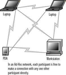
Figure 7.1: An Ad Hoc Network Configuration
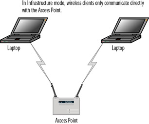
Figure 7.2: Infrastructure Network Configuration
To distinguish different wireless networks from one another, the 802.11 standard defines the Service Set Identifier (SSID). The SSID can be considered the identity element that "glues" together various components of a wireless LAN. Traffic from wireless clients that use one SSID can be distinguished from other wireless traffic using a different SSID. Using the SSID, an AP can determine which traffic is meant for it and which is meant for other wireless networks.
802.11 traffic can be subdivided into three parts:
-
Control frames
-
Management frames
-
Data frames
Control frames include such information as request to send (RTS), clear to send (CTS), and ACK messages. Management frames include beacon frames, probe request/response, authentication frames, and association frames. Data frames are, as the name implies, 802.11 frames that carry data. That data is typically considered network traffic, such as IP encapsulated frames.
Exam 70-124: Objective 3.3.2: Wired Equivalent Privacy
The IEEE 802.11 standard covers the communication between WLAN components. RF poses challenges to privacy in that it travels through and around physical objects. Due to the nature of 802.11 WLANs, the IEEE working group implemented a mechanism to protect the privacy of individual transmissions. The intent was to mirror the privacy found on the WLAN, and the mechanism became known as the Wired Equivalent Privacy protocol, or WEP.
Because WEP utilizes a cryptographic security countermeasure for the fulfillment of its stated goal of privacy, it has the added benefit of becoming an authentication mechanism. This benefit is realized through shared key authentication that allows the encryption and decryption of wireless transmissions. Up to four keys can be defined on an AP or a client. These keys can be rotated to add complexity for a higher-security standard in the WLAN policy.
WEP was never intended to be the absolute authority in wireless security. The IEEE 802.11 standard states that WEP provides for protection from "casual eavesdropping." Instead, the driving force behind WEP is privacy. In cases that require high degrees of security, other mechanisms should be utilized, such as authentication, access control, password protection, and virtual private networks.
Despite its flaws, WEP still offers some level of security, provided that all its features are used properly. This means taking great care in key management, avoiding default options, and ensuring that adequate encryption is enabled at every opportunity.
Proposed improvements in the standard should overcome many of the limitations of the original security options and should make WEP more appealing as a security solution. Additionally, as WLAN technology gains popularity and users clamor for functionality, both the standards committees and the hardware vendors will offer improvements. It is critically important to keep abreast of vendor-related software fixes and changes that improve the overall security posture of a wireless LAN.
With data security enabled in a closed network, the settings on the client for the SSID and the encryption keys have to match the AP when attempting to associate with the network, or the network will fail. The next few sections discuss WEP in its relation to the functionality of the 802.11 standard, including a standard definition of WEP, the privacy created, and the authentication.
WEP provides some security and privacy in transmissions to prevent curious or casual browsers from viewing the contents of the transmissions held between the AP and the clients. In order to gain access, an intruder must be more sophisticated and needs to have specific intent to gain access. Some of the other benefits of implementing WEP include the following:
-
All messages have a CRC-32 checksum calculated that provides some degree of integrity.
-
Privacy is maintained via the RC4 encryption. Without possession of the secret key, the message cannot be easily decrypted.
-
WEP is extremely easy to implement. All that is required is to set the encryption key on the APs and on each client.
-
WEP provides a very basic level of security for WLAN applications.
-
WEP keys are user definable and unlimited. WEP keys can, and should, be changed often.
Creating Privacy with WEP
WEP provides for several implementations: no encryption, 64-bit encryption, and 128-bit encryption. Clearly, no encryption means no privacy. When WEP is set to no encryption, transmissions are sent in cleartext, and they can be viewed by any wireless sniffing application that has access to the RF signal propagated in the WLAN (unless some other encryption mechanism, such as IPSec, is used). In the case of the 64- and 128-bit varieties (just as with password length), the greater the number of characters (bits), the stronger the encryption. The initial configuration of the AP includes the setup of the shared key. This shared key can be in the form of either alphanumeric or hexadecimal strings and must be matched on the client.
WEP uses the RC4 encryption algorithm, a stream cipher developed by Ron Rivest of RSA Security (rsasecurity.com). Both the sender and receiver use the stream cipher to create identical pseudorandom strings from a known shared key. The process entails having the sender logically XOR the plaintext transmission with the stream cipher to produce the ciphertext. The receiver takes the shared key and identical stream and reverses the process to gain the plaintext transmission.
| Note | XOR, or exclusive OR, is a Boolean logic operator that returns a value of TRUE only if one of its operands is true, as opposed to an inclusive OR, which returns a value of TRUE if either of its operands are true. |
The Boolean logic involved in the WEP process can become extremely complex and is not something that most wireless network users, administrators included, will ever get into. The discussion is presented here only for the sake of briefly explaining how WEP functions, which helps to understand how it can be cracked with the right tools and the right amount of time. The steps in the process are as follows:
-
The plaintext message is run through an integrity check algorithm (the 802.11 standard specifies the use of CRC-32) to produce an integrity check value (ICV).
-
The ICV is appended to the end of the original plaintext message.
-
A "random" 24-bit initialization vector (IV) is generated and prepended to (added to the beginning of) the secret key which is then input to the RC4 Key Scheduling Algorithm (KSA) to generate a seed value for the WEP pseudo-random number generator (PRNG).
-
The WEP PRNG outputs the encrypting cipher stream.
-
This cipher stream is then XORed with the plaintext/ICV message to produce the WEP ciphertext.
-
The ciphertext is then prepended with the IV (in plaintext), encapsulated, and transmitted.
A new IV is used for each frame to prevent the key's reuse weakening the encryption. This means that for each string generated, a different value is used for the RC4 key. Although this is a secure policy in itself, its implementation in WEP is flawed because of the nature of the 24-bit space. The space is so small with respect to the potential set of IVs that in a short period of time, all keys are reused. When this happens, two different messages are encrypted with the same IV and key, and the two messages can be XORed with each other using specially crafted WEP cracking tools to cancel out the key stream, allowing an attacker who knows the contents of one message to easily figure out the contents of the other. Unfortunately, this weakness is the same for both the 40- and 128-bit encryption levels because both use the 24-bit IV.
To protect against some rudimentary attacks that insert known text into the stream to attempt to reveal the key stream, WEP incorporates a checksum in each frame. Any frame not found to be valid through the checksum is discarded.
Authentication
There are two authentication methods in the 802.11 standard:
-
Open authentication
-
Shared-key authentication
Open authentication is most precisely described as device-oriented authentication and can be considered a null authentication; all requests are granted. Without WEP, open authentication leaves the WLAN wide open to any client who knows the SSID. With WEP enabled, the WEP secret key becomes the indirect authenticator.
The shared-key authentication process shown in Figure 7.3 is a four-step process that begins when the AP receives the validated request for association. After the AP receives the request, a series of management frames is transmitted between the stations to produce the authentication. This includes the use of the cryptographic mechanisms employed by WEP as a validation. The four steps break down in the following manner:
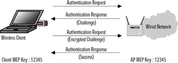
Figure 7.3: Shared-Key Authentication
-
The requestor (the client) sends a request for association.
-
The authenticator (the AP) receives the request and responds by producing a random challenge text and transmitting it back to the requestor.
-
The requestor receives the transmission, encrypts the challenge with the secret key, and transmits the encrypted challenge back to the authenticator.
-
The authenticator decrypts the challenge text and compares the values against the original. If they match, the requestor is authenticated. On the other hand, if the requestor doesn't have the shared key, the cipher stream cannot be reproduced. Therefore, the plaintext cannot be discovered, and theoretically, the transmission is secured.
One of the greatest weaknesses in shared-key authentication is the fact that it provides an attacker with enough information to try to crack the WEP secret key. The challenge, which is sent from authenticator to requestor, is sent in the clear. The requesting client then transmits the same challenge, encrypted using the WEP secret key, back to the authenticator. An attacker who captures both of these packets has two pieces to a three-piece puzzle: the cleartext challenge and the encrypted ciphertext of that challenge. The algorithm, RC4, is also known. All that is missing is the secret key.
To determine the key, the attacker simply tries a brute-force search of the potential key space using a dictionary attack. At each step, the attacker tries to decrypt the encrypted challenge with a dictionary word as the secret key. The result is then compared against the authenticator's challenge. If the two match, the attacker has determined the secret key. In cryptography, this attack is called a known-plaintext attack and is the primary reason that shared-key authentication is considered slightly weaker than open authentication.
Exam 70-124: Objective 3.3.2: 802.1x Authentication
The current IEEE 802.11b standard is severely limited because it is available only for the current open and shared key authentication scheme, which is nonextensible. To address the weaknesses in the authentication mechanisms we've discussed, several vendors (including Cisco and Microsoft) adopted the IEEE 802.1x authentication mechanism for wireless networks.
The IEEE 802.1x standard was created for the purpose of providing a security framework for port-based access control that resides in the upper layers of the protocol stack. The most common method for port-based access control is to enable new authentication and key management methods without changing current network devices. The benefits that are the end result of this work include the following:
-
There is a significant decrease in hardware cost and complexity.
-
There are more options, allowing administrators to pick and choose their security solutions.
-
The "latest and greatest" security technology can be installed and it should still work with the existing infrastructure.
-
You can respond quickly to security issues as they arise.
| Exam Warning | The 802.1x standard typically is relevant to wireless networks due to the fact that it is quickly becoming the standard method of securely authenticating on a wireless network. However, do not confuse 802.1x with 802.11x. |
When a client device connects to a port on an 802.1x capable AP, the AP port can determine the authenticity of the devices. Before discussing the workings of the 802.1x standard, we must define some terminology. In the context of 802.1x, the following terms have these meanings:
-
Port A port is a single point of connection to the network.
-
Port access entity (PAE) The PAE controls the algorithms and protocols that are associated with the authentication mechanisms for a port.
-
Authenticator PAE The authenticator PAE enforces authentication before it will allow access to resources located off that port.
-
Supplicant PAE The supplicant PAE tries to access the services that are allowed by the authenticator.
-
Authentication server The authentication server is used to verify the supplicant PAE. It decides whether or not the supplicant is authorized to access the authenticator.
-
Extensible Authentication Protocol Over LAN (EAPOL) The 802.1x standard defines a standard for encapsulating Extensible Authentication Protocol (EAP) messages so that they can be handled directly by a LAN MAC service. 802.1x tries to make authentication more encompassing rather than enforcing specific mechanisms on the devices. For this reason, 802.11x uses EAP to receive authentication information.
-
Extensible Authentication Protocol Over Wireless (EAPOW) When EAPOL messages are encapsulated over 802.11 wireless frames, they are known as EAPOW.
So What Are 802.1x and 802.11x, Exactly?
Wireless technology provides convenience and mobility, but it also poses massive security challenges for network administrators, engineers, and security administrators. Security for 802.11 networks can be broken into three distinct components:
-
The authentication mechanism
-
The authentication algorithm
-
Data frame encryption
Current authentication in the 802.11 IEEE standard is focused more on wireless LAN connectivity than on verifying user or station identity. Since wireless can potentially scale so high in terms of the number of possible users, you might want to consider a way to centralize user authentication, and this is where the IEEE 802.1x standard comes into play.
The 802.1x works in a similar fashion both for EAPOL and EAPOW. As shown in Figure 7.4, the EAP supplicant (in this case, the wireless client) communicates with the AP over an "uncontrolled port." The AP sends an EAP-request/identity to the supplicant as well as a Remote Access Dial-In User Service (RADIUS)-access-request to the RADIUS access server. The supplicant responds with an identity packet, and the RADIUS server sends a challenge based on the identity packets sent from the supplicant. The supplicant provides its credentials in the EAP-response that the AP forwards to the RADIUS server. If the response is valid and the credentials are validated, the RADIUS server sends a RADIUS-access-accept to the AP, which then allows the supplicant to communicate over a "controlled" port. This is communicated by the AP to the supplicant in the EAP-success packet.
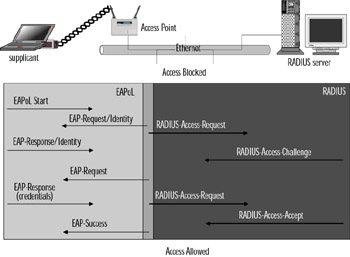
Figure 7.4: EAPOL Traffic Flow
User Identification and Strong Authentication
With the addition of the 802.1x standard, clients are identified by usernames, not by the MAC addresses of the devices. This design not only enhances security, it also streamlines the process for authentication, authorization, and accountability for the network. The 802.1x standard was designed so that it could support extended forms of authentication, using password methods (such as one-time passwords, or GSS_API mechanisms such as Kerberos) and nonpassword methods (such as biometrics, Internet Key Exchange [IKE], and smartcards).
Dynamic Key Derivation
The 802.1x standard allows for the creation of per-user session keys. With 802.1x, WEP keys do not need to be kept at the client device or AP. These WEP keys will be dynamically created at the client for every session, thus making it more secure. The Global key, like a broadcast WEP key, can be encrypted using a unicast session key and then sent from the AP to the client in a much more secure manner.
Mutual Authentication
The 802.1x standard and EAP provide for a mutual authentication capability. This capability makes the clients and the authentication servers mutually authenticating end points and assists in the mitigation of attacks from man-in-the-middle types of devices. Any of the following EAP methods provides for mutual authentication:
-
TLS This requires that the server supply a certificate and establish that it has possession of the private key.
-
IKE This requires that the server show possession of a preshared key or private key. (This can be considered certificate authentication.)
-
GSS_API (Kerberos) This requires that the server can demonstrate knowledge of the session key.
Per-Packet Authentication
EAP can support per-packet authentication and integrity protection, but this authentication and integrity protection are not extended to all types of EAP messages. For example, negative acknowledgment (NAK) and notification messages are not able to use per-packet authentication and integrity. Per-packet authentication and integrity protection work for the following (packet is encrypted unless otherwise noted):
-
TLS and IKE derived session key
-
TLS ciphersuite negotiations (not encrypted)
-
IKE ciphersuite negotiations
-
Kerberos tickets
-
Success and failure messages that use a derived session key (through WEP)
Preventing Dictionary Attacks Using EAP
EAP can be employed in your wireless network to add security by preventing offline dictionary attacks against network passwords. When choosing an EAP type, consider the use of EAP-TLS. EAP-TLS is a PKI based authentication method that uses digital certificates for user verification and provides for mutual authentication without the need for username and password entry, thereby mitigating the possibility of a dictionary attack. EAP-MD5 is not recommended for securing wireless connections because it relies on a standard challenge/response authentication method using a username and password combination, which opens you up to dictionary attacks which are precisely what you are attempting to prevent.
| Test Day Tip | You might find it helpful to write out a table showing the various authentication methods used in 802.11 networks (such as open authentication, shared-key authentication, and 802.1x authentication) with the various properties that each of these authentication methods require. This table will help keep them straight in your mind when you take the test. |
|
|
EAN: 2147483647
Pages: 162